-14-
Model G4000 (Mfg. Since 8/09)
Moving & placing
Lathe
to ensure the lathe does not unexpectedly move
during operation, you must securely mount the
machine to a flat and stable surface that can sup-
port the weight. to do this, use the chip pan as a
template to drill the holes (refer to
Mounting on
page 15).
To move and place your lathe:
1. remove the crate top, then remove the chip
pan that is attached to it.
2. remove the sides of the crate, the toolbox,
and the faceplate/4-jaw chuck assembly from
the shipping pallet, then unbolt the lathe from
the pallet.
3. position the chip pan on the prepared sur-
face, use it as a template to mark the mount-
ing hole locations, then drill the holes.
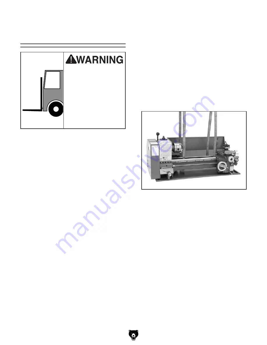
4. Wrap the lifting straps around the back of the
bedway and up through the center cavities
to avoid bending the leadscrew or contacting
the carriage controls when lifting, as shown in
figure 6.
Note:
To help balance the load, remove the
tailstock and steady rest from the machine,
then position the right lifting strap and the
carriage as far to the right as possible (refer
Carriage Controls on Page 19 for detailed
instructions).
Make sure the lifting straps do not put any
strain on the leadscrew or carriage controls.
5. Attach the lifting straps to the power lifting
equipment, have an assistant steady the load,
then lift it just enough to clear any obstacles
and move it to its mounting position.
6. properly mount the lathe as instructed in the
Mounting subsection on page 15.
figure 6. Lifting straps properly positioned.
The Model G4000 is a
heavy machine. Serious
personal injury may occur
if safe moving methods
are not used. To be safe,
get assistance, use safe
lifting methods, and use
power equipment that
is rated for at least 500
lbs. to move the shipping
crate and machine.


