


G0803
(Mfd. Since 09/15)
-39-
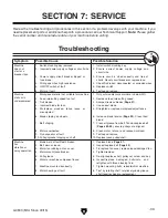
Review the troubleshooting and procedures in this section if a problem develops with your machine. If you
need replacement parts or additional help with a procedure, call our Technical Support.
Note: Please gather
the serial number and manufacture date of your machine before calling.
SECTION 7: SERVICE
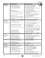
Troubleshooting
Symptom
Possible Cause
Possible Solution
Machine
does not
start or a
breaker trips.
1. Switch disabling key removed.
2. Incorrect power supply voltage or circuit size.
3. Power supply circuit breaker tripped or
fuse blown.
4. Wiring open/has high resistance.
5. ON/OFF switch at fault.
6. Motor at fault.
1. Install switch disabling key.
2. Ensure correct power supply voltage and
circuit size.
3. Ensure circuit is sized correctly and free of
shorts. Reset circuit breaker or replace fuse.
4. Check/fix broken, disconnected, or corroded wires.
5. Replace switch.
6. Test/repair/replace.
Machine
stalls or is
underpowered.
1. Workpiece material not suitable for machine.
2. Feed rate/cutting speed too fast.
3. Dull blades.
4. Incorrect blade for task.
5. Workpiece crooked; fence loose or
misadjusted.
6. Blade slipping on wheels.
7. Belt slipping.
8. Motor overheated.
9. Run capacitor at fault.
10. Pulley/sprocket slipping on shaft.
1. Only cut wood/ensure moisture is below 20%.
2. Decrease feed rate/cutting speed.
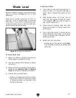
3 Sharpen/replace blades (
Page 31).
4. Use correct blade.
5. Straighten or replace workpiece/adjust fence.
6. Increase blade tension (
Page 20). Clean tires/
blade.
7. Clean oil/grease from belt. Tension/replace belt
(
Pages 42–43); ensure pulleys are aligned.
8. Clean motor, let cool, and reduce workload.
9. Test/repair/replace.
10. Replace loose pulley/shaft.
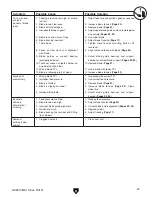
Machine
has
vibration or
noisy operation.
1. Blade weld at fault/teeth broken.
2. Belt worn or loose.
3. Motor fan rubbing on fan cover.
4. Motor mount loose/broken.
5. Pulley loose.
6. Motor or machine component loose.
7. Machine mounted incorrectly.
8. Motor bearings at fault.
1. Replace blade (
Page 31).
2. Inspect/replace belt (
Page 43).
3. Fix/replace fan cover; replace loose/damaged fan.
4. Tighten/replace.
5. Re-align/replace shaft, pulley set screw, and key.
6. Inspect/replace damaged bolts/nuts, and
retighten with thread locking fluid.
7. Tighten mounting bolts; relocate/shim machine.
8. Test by rotating shaft; rotational grinding/loose
shaft requires bearing replacement.
Содержание G0803
Страница 56: ...54 G0803 Mfd Since 09 15...
Страница 60: ......