


G0803
(Mfd. Since 09/15)
-23-
Adjusting Blade
Guide Bearings
Properly adjusting the blade guides provides side-
to-side support to help keep the blade straight
while cutting.
There are blade guide bearings on the upper and
lower blade guide assemblies. Both adjust in the
same manner. The following instructions refer to
the upper guide bearings. To access the lower
guide bearings, you must open the lower wheel
guard (see
Page 3 for reference).
Important: Make sure the blade is tracking and
tensioned correctly before performing this proce-
dure (see
Tensioning Blade on Page 20).
Tool Needed
Qty
Hex Wrench 4mm .............................................. 1
To adjust blade guides:
1. DISCONNECT MACHINE FROM POWER!
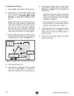
Blade
Guide
Bearing
Blade
Gullets
Approximately
0.016"
Figure 26. Blade guide bearing positioned just
behind blade gullets.
Note: With wider blades, it may not be possi-
ble to bring the guide bearings just behind the
blade gullets. Position them as far forward as
possible without allowing the guide bearing
housing to touch the back of the blade.
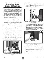
Blade teeth are angled out slightly, protrud-
ing wider than the blade thickness; this
is known as blade "tooth set" (see Figure
27). If teeth contact guide bearings during
operation, damage may occur. Therefore,
the support bearing must be set to prevent
teeth from contacting guide bearings during
operation (refer to Page 22 for details).
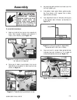
2. Loosen guide block cap screw shown in
Figure 25, then laterally position guide bear-
ings just behind blade gullets, as illustrated
in
Figure 26, then re-tighten cap screw to
secure setting.
Figure 25. Upper guide bearing components.
Guide Bearing
Adjustment
Cap Screws
Guide Bearing
(1 of 2)
Guide Block
Cap Screw
“Tooth Set”
Wider Than
Blade Thickness
BladeThickness
Figure 27. Illustration of blade "tooth set".
Содержание G0803
Страница 56: ...54 G0803 Mfd Since 09 15...
Страница 60: ......