-4-
Model G0767 (Mfd. Since 1/14)
Controls &
Components
Refer to
Figures 1–2 and the following descrip-
tions to become familiar with the basic controls of
this machine.
To reduce your risk of
serious injury, read this
entire manual BEFORE
using machine.
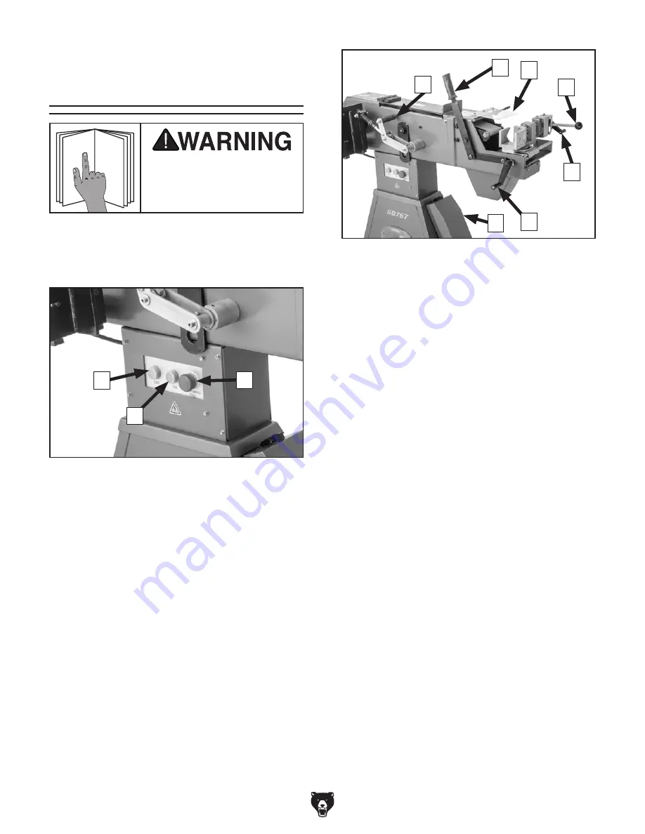
Figure 1. Control panel.
A
B
C
A. Abrasive Belt OFF Button
B. Abrasive Belt ON Button
C. Emergency Stop Button: Cuts power to the
motor and remains depressed until reset.
Twist clockwise until it pops out to reset.
D. Belt Tension Lever: Controls abrasive belt
tension.
E. Feed Lever: Moves tube toward or away
from abrasive belt.
F. Spark Shield Lock Handle: Secures spark
shield in place.
G. Clamp Lever: Locks tube between vise jaws
so it will not move during grinding.
H. Clamp Crank: Adjusts distance between
jaws and clamp plate to accommodate diam-
eter of tube.
I. Traverse Crank: Moves tube from side-to-
side across abrasive belt. This will increase
the life of the belt.
J. Profile Roller Storage Cabinet: Safely
stores profile rollers away from debris and
grime.
Figure 2. Other controls.
D
E
F
G
H
I
J
Содержание G0767
Страница 48: ......


