Grizzly G0634X Скачать руководство пользователя страница 50

-48-

Model G0634X (Mfd. Since 11/20)

Checking Planer 

Table Parallelism

Table Parallelism Inspection

The easiest way to check that your planer table is 

parallel with the headstock is to plane a workpiece 

and then measure its thickness in multiple loca-

tions. Extra care must be taken to ensure accu-

racy. If the workpiece is tapered from left-to-right 

or from front-to-back, then parallelism may be a 

problem.  If the table  is not within the maximum 

allowable tolerances, it must be adjusted.

Table Parallelism Adjustments

Items Needed: 

Qty

Rotacator ........................................................... 1

Wrench 12mm ................................................... 1

Hex Wrench 4, 8mm ....................................1 Ea.

To adjust table parallelism:

1. 

DISCONNECT MACHINE FROM POWER!

2.

  Raise planer table as far as possible.

3.

  Loosen (4) cap screws on cylinder liner, as 

shown in Figure 69.

Table parallelism is critical to the operation of the 

planer. As such, it is essential that the planer table 

is parallel with the cutterhead (within 0.002") from 

side-to-side, as illustrated in Figure 67. 

Figure 67. 

Side-to-side parallelism of table and 

cutterhead.

Cutterhead

Table

Parallel

Parallel

SIDE-TO-SIDE

Table

NOT Parallel

NOT Parallel

(Front View)

Cutterhead

Figure 68. 

Front-to-back parallelism.

Table

Table

Head

Head

Parallel

Parallel

Not-Parallel

Not-Parallel

FRONT

BACK

How the planer table sits in relation to the head 

casting from front-to-back is also important (see 

Figure  68

). The tolerances on the front-to-back 

positioning are not as critical as the cutterhead/

table side-to-side positioning. Therefore, the max-

imum allowable tolerance for the front-to-back 

parallelism is not more than 0.020".

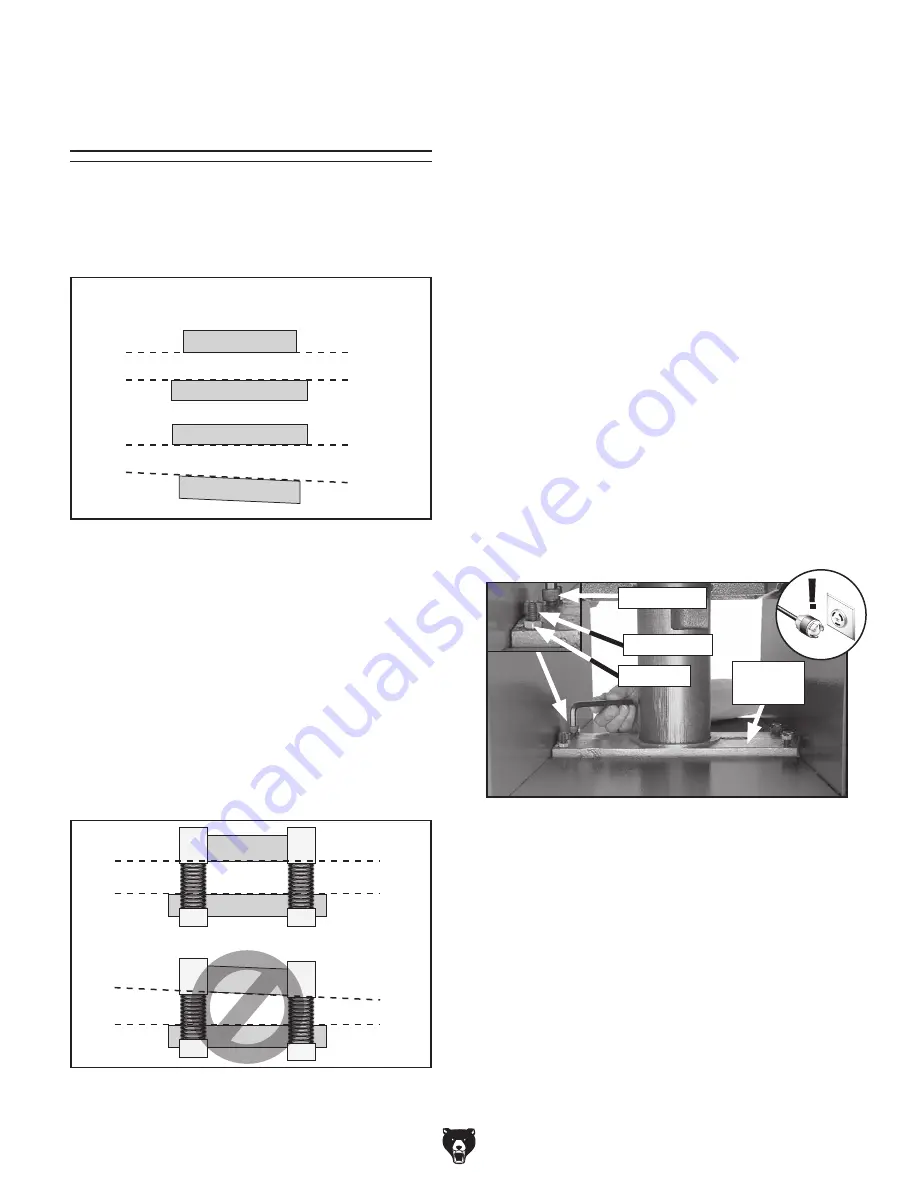
— If table is not parallel to cutterhead side-to-

side (see Figure 69), loosen (2) lock nuts 

on right or left side of cylinder liner. Adjust 

set screws to raise or lower table so it is 

parallel to cutterhead.

— If table is not parallel to cutterhead front-

to-back  (see  Figure  69), loosen (2) lock 

nuts at front or back of cylinder liner. 

Adjust set screws to raise or lower front or 

back of table so it is parallel to cutterhead. 

4.

  Tighten (4) cap screws on cylinder liner.

Figure 69

. Adjusting table parallelism.

Lock Nut

Set Screw

Cap Screw

Cylinder

Liner

Maximum Allowable Tolerances:

Cutterhead/Table Side-to-Side ..................0.002"

Head Casting/Table Front/Back ................0.020"

Содержание G0634X

Страница 1: ...ORTION OF THIS MANUAL MAY BE REPRODUCED IN ANY SHAPE OR FORM WITHOUT THE WRITTEN APPROVAL OF GRIZZLY INDUSTRIAL INC BL8977 PRINTED IN TAIWAN V5 04 22 MODEL G0634X 12 JOINTER PLANER W V HELICAL CUTTERH...

Страница 2: ...g grinding tool integrity and the usage of personal protective equipment The manufacturer will not be held liable for injury or property damage from negligence improper training machine modifications...

Страница 3: ...evel Cutting On Jointer 31 Jointer Planer Conversion 32 Planing Tips 33 Common Planing Problems 34 Setting Planer Depth of Cut 35 SECTION 5 ACCESSORIES 36 SECTION 6 MAINTENANCE 37 Schedule 37 Cleaning...

Страница 4: ...ade every effort to be exact with the instruc tions specifications drawings and photographs in this manual Sometimes we make mistakes but our policy of continuous improvement also means that sometimes...

Страница 5: ...of 2 Infeed Table Jointer Depth of Cut Scale Cutterhead Guard Outfeed Table Thickness Scale Planer Dust Port Fence Jointer Planer Selection Lever For Your Own Safety Read Instruction Manual Before Ope...

Страница 6: ...eight Lock Secures infeed table height adjustment requires 6mm hex wrench Figure 2 Location of infeed jointer table adjustment controls Figure 3 Location of outfeed jointer table adjustment controls F...

Страница 7: ...h of tables loosens to allow adjustment Jointer Fence Controls Figure 5 Location of 45 fence stop L 45 Fence Stop Allows fence to be quickly positioned at 45 when adjusting tilt setting Figure 4 Locat...

Страница 8: ...ons of planer controls P Jointer Planer Selection Lever Moves UP to engage feed rollers for planer operation Moves DOWN to disengage feed rollers for jointer operation Figure 9 Location of jointer pla...

Страница 9: ...urrent Rating 25A Minimum Circuit Size 30A Connection Type Cord Plug Power Cord Included Yes Power Cord Length 10 ft Power Cord Gauge 12 AWG Plug Included No Recommended Plug Type L6 30 Switch Magneti...

Страница 10: ...2 5mm Cutterhead Speed 5034 RPM Table Information Jointer Table Length 59 1 2 in Table Width 14 in Table Thickness 1 5 8 in Floor to Table Height 35 1 2 in Adjustment Type Knob Table Information Plan...

Страница 11: ...d proof DANGEROUS ENVIRONMENTS Do not use machinery in areas that are wet cluttered or have poor lighting Operating machinery in these areas greatly increases the risk of accidents and injury MENTAL A...

Страница 12: ...moving parts or flying debris Make sure they are properly installed undamaged and working correctly BEFORE operating machine FORCING MACHINERY Do not force machine It will do the job safer and better...

Страница 13: ...e risk of kickback It also requires more cutting force which produces chat ter or excessive chip out Always joint or surface plane WITH the grain CUTTING LIMITATIONS Cutting workpieces that do not mee...

Страница 14: ...long stock SECURE KNIVES INSERTS Loose knives or improperly set inserts can become dangerous projectiles or cause machine damage Always verify knives inserts are secure and properly adjusted before op...

Страница 15: ...y result especially if connected to an undersized circuit To reduce the risk of these hazards avoid over loading the machine during operation and make sure it is connected to a power supply circuit th...

Страница 16: ...requirements or if you are in doubt about whether the tool is properly grounded If you ever notice that a cord or plug is damaged or worn discon nect it from power and immediately replace it with a ne...

Страница 17: ...s per person 1 Pair Lifting Equipment Min 800 lb Capacity 1 Lifting Sling 800 lb Capacity Optional 1 Dust Collection System 1 Dust Hose 4 length as needed 1 Hose Clamp 4 1 Shop Rags for Cleaning As Ne...

Страница 18: ...If you cannot find an item on this list care fully check around inside the machine and packaging materials Often these items get lost in packaging materials while unpack ing or they are pre installed...

Страница 19: ...the following Disposable rags Cleaner degreaser WD 40 works well Safety glasses disposable gloves Plastic paint scraper optional Basic steps for removing rust preventative 1 Put on safety glasses 2 C...

Страница 20: ...d in this manual See below for required space allocation Physical Environment The physical environment where the machine is operated is important for safe operation and lon gevity of machine component...

Страница 21: ...strap holes this will perma nently alter your machine If you are unsure how to lift this machine consult a qualified professional Figure 16 Locations of front and right rear lifting holes and shippin...

Страница 22: ...n Minimum CFM at Dust Port 400 CFM Do not confuse this CFM recommendation with the rating of the dust collector To determine the CFM at the dust port you must consider these variables 1 CFM rating of...

Страница 23: ...information DO NOT operate or allow others to operate machine until the information is understood To test run machine 1 Clear all setup tools away from machine 2 Press Emergency Stop button in 3 Make...

Страница 24: ...belts to avoid slippage and burn out Refer to Page 42 when you are ready to perform this important adjustment Note Pulleys and belts can get hot This is a nor mal condition Allow them to cool before m...

Страница 25: ...f machine WE STRONGLY RECOMMEND that you seek additional training outside of this manual Read books magazines or get formal training before beginning any proj ects Regardless of the content in this se...

Страница 26: ...ever as long as you move handwheel in same direction dur ing operation backlash will not be a factor Typical Planing Operation 5 When all safety precautions have been taken turns planer ON 6 Stands to...

Страница 27: ...ts and poor cutting results Excess moisture can also hasten rust and corrosion Scrape all glue off of boards before planing Keep work area clear Stock Inspection Requirements With Grain Against Grain...

Страница 28: ...ffectively take with each pass The chart in the figure below shows the Janka Hardness Rating for a number of commonly used species The larger the number the harder the workpiece and the less material...

Страница 29: ...ive to the carbide inserts at TDC top dead center The jointer depth of cut scale see Figure 27 goes up to 3 16 however the recommended depth of cut per pass is 1 16 1 8 depending on the operation Adju...

Страница 30: ...olves four steps performed in the order below 1 Surface Plane on Jointer Concave face of workpiece is surface planed flat with jointer Squaring stock means making it flat and paral lel along both leng...

Страница 31: ...whenever practical to further reduce risk of accidental hand contact with cutterhead 3 Set fence to 90 4 Start jointer 5 Place workpiece firmly against fence and infeed table CAUTION To ensure workpie...

Страница 32: ...ing the entire cut Instead of allowing a hand to pass directly over cut terhead lift it up and over cutterhead and safely reposition it on the outfeed side to con tinue supporting workpiece Use push b...

Страница 33: ...of the cutterhead lift it up and over cutterhead and place push block on portion of the workpiece once it is 4 past cutterhead Now focus your pressure on outfeed end of the workpiece while feeding an...

Страница 34: ...e Lock Lever Figure 34 Infeed table pivoted up The Model G0634X is ready for jointer operations after it is first setup To use the machine as a plan er you must convert it from a jointer to a planer F...

Страница 35: ...main sharp much longer To avoid chip marks always plane WITH the grain direction of the wood Never plane cross grain or end grain Plane ONLY natural wood fiber Do not plane wood composites or other ma...

Страница 36: ...ly as it leaves the outfeed end of the planer The best way to deal with snipe is by planing lumber longer than your intended work length and then cutting off the excess after planing is completed Pitc...

Страница 37: ...stance is the thickness of the workpiece minus the depth of cut The planing depth of cut is controlled by using the table height handwheel on the right side of the machine Rotating the handwheel clock...

Страница 38: ...e Power Twist V belts can be customized in minutes to any size just add or remove sections to fit your needs Requires two Power Twist V belts to replace the stock V belts on your Model G0634X Figure 3...

Страница 39: ...Cleaning the Model G0634X is relatively easy Vacuum excess wood chips and sawdust and wipe off the remaining dust with a dry cloth If any resin has built up use a resin dissolving cleaner to remove it...

Страница 40: ...otation of the leadscrew see Figure 43 Remove the leadscrew access panel see Figure 44 to access these parts Clean and apply a thin coat of ISO 68 machine oil to the outside surface of the column and...

Страница 41: ...Equivalent Oil Amount 1 2 Drops Frequency As Needed The jointer infeed and outfeed table elevation knobs and pivot points require periodic lubrica tion Raise and secure tables in up position and lubri...

Страница 42: ...otor decreases rapidly with load overheats or stalls 1 Motor run capacitor at fault 2 Motor overloaded during operation 3 Air circulation through the motor restricted 4 Motor overloaded during operati...

Страница 43: ...ways reduce cutting depth when surface planing or working with hardwoods Fuzzy grain 1 Wood may have high moisture content or surface wetness 2 Dull inserts 1 Check moisture content and allow to dry i...

Страница 44: ...NECT MACHINE FROM POWER 2 Remove motor access panel on back of machine see Figure 49 Note A collection of black belt dust inside motor compartment is normal during life of belts Figure 50 Checking V b...

Страница 45: ...all motor access panel from Step 2 on Note After first 16 hours of belt life re ten sion belts as they will stretch and seat during this time Figure 52 Removing V belt tension for belt removal replace...

Страница 46: ...arbide inserts when they are at top dead center If the outfeed table is set too low the workpiece will be tapered from front to back If the outfeed table is set too high the workpiece will hit the edg...

Страница 47: ...tfeed Table Parallelism 1 DISCONNECT MACHINE FROM POWER 2 Put on heavy leather gloves then remove cutterhead guard and fence 3 Place straightedge on outfeed table so it hangs over cutterhead in one of...

Страница 48: ...le and adjust infeed table even with outfeed table as shown in Figure 61 2 Raise stop bolts just enough so front edge of table is higher than cutterhead then adjust each stop bolt 1 6 turn clockwise t...

Страница 49: ...ten cap screw Shimming top position will raise rear cutterhead side of table shim ming lower position will raise rear infeed side 6 Repeat Step 3 with each of the remaining straightedge positions and...

Страница 50: ...utterhead Cutterhead Table Parallel Parallel SIDE TO SIDE Table NOT Parallel NOT Parallel Front View Cutterhead Figure 68 Front to back parallelism Table Table Head Head Parallel Parallel Not Parallel...

Страница 51: ...nd cutterhead pocket from which insert was removed and replace insert so fresh sharp edge is facing outward Note Proper cleaning is critical to achieving smooth finish Dirt or dust trapped between ins...

Страница 52: ...tfeed table Straightedge Infeed Outfeed Figure 73 Depth scale adjusted to 0 position Depth Scale Pointer Depth Scale Calibrating Depth Scale Setting Fence Stops The fence stops simplify the task of ad...

Страница 53: ...k table by moving it up and down Adjust set screw as needed until friction of table movement is balanced between minimal play and ease of move ment then secure gib nut Note Tighter gibs reduce play bu...

Страница 54: ...turn clockwise to decrease spring tension Figure 78 Spring tension screws Tension Screws Anti Kickback Fingers Figure 90 Location of anti kickback fingers Anti Kickback Fingers The anti kickback finge...

Страница 55: ...t at the time of printing but may not match your machine If you find this to be the case use the wiring diagram inside the motor junction box CAPACITORS INVERTERS Some capacitors and power inverters s...

Страница 56: ...ON 3 4 T2 4 L1 1 L3 5 NO13 L2 3 5 6 95 18 22 26 RESET NC21 SDE NC22 MAGNETIC SWITCH ASSEMBLY Ground RA 30 220V MOTOR Ground Hot 3 4 2 1 LIMIT SWITCH EMERGENCY STOP BUTTON G X Y Hot L6 30 PLUG as reco...

Страница 57: ...nce 11 20 55 READ ELECTRICAL SAFETY ON PAGE 53 Electrical Component Photos Figure 79 Magnetic switch Figure 81 Start capacitor Figure 82 Run capacitor Figure 83 Jointer table limit switch Figure 80 Em...

Страница 58: ...t all parts shown are available for purchase Call 800 523 4777 or visit www grizzly com parts to check for availability Stand 26 5 5 1 5 2 9 7 8 7 8 6 21 1 1 1 21 1 2 10 52 51 22 23 29 31 17 14 6 1 8...

Страница 59: ...9 5 P0634X029 5 ON BUTTON 10 P0634X010 PLANER SCALE 29 6 P0634X029 6 OFF BUTTON 12 P0634X012 REINFORCEMENT PLATE 30 P0634X030 PHLP HD SCR 10 24 X 5 8 12 1 P0634X012 1 HEX BOLT 5 16 18 X 1 31 P0634X031...

Страница 60: ...OUTFEED TABLE ADJ KNOB 133 P0634X133 KNOB 108 P0634X108 GUIDE SCREW 134 P0634X134 PUSH BLOCK SMALL 109 P0634X109 HEX NUT 1 2 12 135 4 P0634X135 4 L BRACKET 110 P0634X110 INFEED HANDGRIP 135 5 P0634X1...

Страница 61: ...8 SET SCREW M5 8 X 4 206 P0634X206 OUTFEED ROLLER 229 P0634X229 SET SCREW 1 4 20 X 3 4 CONE PT 207 P0634X207 INFEED ROLLER 230 P0634X230 MOTOR 5HP 220V 1 PH 208 P0634X208 COVER 230 1 P0634X230 1 JUNCT...

Страница 62: ...T SCREW 1 4 20 X 1 307 P0634X307 BALL BEARING 6204 2RS 327 P0634X327 HEX NUT 1 4 20 308 P0634X308 TENSION SPRING 328 P0634X328 CAP SCREW 5 16 18 X 2 309 P0634X309 BALL BEARING 608 2RS 329 P0634X329 FL...

Страница 63: ...8MM 407 P0634X407 GEAR BOX 426 P0634X426 ROLL PIN 5 X 30 408 P0634X408 BUSHING 427 P0634X427 SET SCREW 5 16 18 X 1 4 408 1 P0634X408 1 SELF LUBRICATING SHLDR BUSHING 428 P0634X428 FLAT WASHER 408 2 P0...

Страница 64: ...1 2 SWING LEVER M 509 P0634X509 HEX BOLT 5 16 18 X 1 501 3 P0634X501 3 LIMIT SWITCH BRACKET 510 P0634X510 HEX BOLT 5 16 18 X 1 2 502 P0634X502 COMPRESSION SPRING 511 P0634X511 HEX NUT 5 16 18 503 P063...

Страница 65: ...0634X625 FENCE SUPPORT 607 P0634X607 PHLP HD SCR M4 7 X 6 626 P0634X626 FENCE SUPPORT PLATE 608 P0634X608 REAR GUARD CONNECTOR 627 P0634X627 FLAT HD SCR 10 24 X 3 8 608 1 P0634X608 1 REAR GUARD LINK 6...

Страница 66: ...NUMBER LABEL 803 P0634X803 CUTTERHEAD WARNING LABEL 811 P0634X811 TABLE LOCK KNOB NOTICE 804 P0634X804 EAR PROTECTION LABEL 812 P0634X812 CHANGE LEVER LABEL 805 P0634X805 DISCONNECT POWER LABEL 813 P0...

Страница 67: ...rty or for incidental contingent special or consequential damages arising from the use of our products The manufacturers reserve the right to change specifications at any time because they constantly...

Страница 68: ......

Отзывы: