


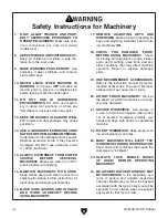


G0510Z 3⁄4 HP Shaper
-13-
Stand
Figure 6.
Attaching cross braces to stand side.
Components and Hardware Needed:
Qty
Shaper Assembly .............................................. 1
Stand Sides w/Feet ........................................... 2
Stand Cross Braces .......................................... 2
Carriage Bolts
5
⁄
16
"-18 x
1
⁄
2
" .............................. 16
Flat Washers
3
⁄
8
" .............................................. 16
Hex Nuts
5
⁄
16
"-18 .............................................. 16
To assemble the stand:
1.
Lay one stand side on the ground and attach
the two cross braces with four of the carriage
bolts, washers, and hex nuts as shown in
Figure 6
.
DO NOT fully tighten the nuts and
bolts at this time.
Figure 8.
Attaching stand to shaper unit.
Figure 7.
Stand fully assembled.
2.
Attach the remaining stand side to the other
end of the cross braces in the same manner
as
step 1
. The stand assembly should now
look like
Figure 7
.
3.
Place the shaper table upside down on the
two 4x4 blocks, as shown in
Figure 8
. Make
sure the spindle DOES NOT touch the ground
or the weight of the shaper may damage the
spindle.
4.
Place the stand assembly on the shaper and
attach it with the remaining eight carriage
bolts, washers and hex nuts, as shown in
Figure 8
.
5.
Have an assistant help you turn the shaper
unit rightside-up.
6.
Level the shaper, then tighten all of the
assembly bolts on the stand.
Note:
Sheet steel will often “spring” after it has
been fabricated at the factory, occasionally mak-
ing it difficult to line up precisely with other parts.
Do not be surprised if the stand requires a bit of
“persuasion” to fit together. On the other hand, if
the parts just do not seem to work together, try
switching parts around (such as cross braces).
Содержание G0510Z
Страница 14: ...G0510Z 3 4 HP Shaper 11 Hardware Recognition Chart ...
Страница 38: ...G0510Z 3 4 HP Shaper 35 G0510Z Electrical Components Wiring ...
Страница 44: ......


