-38-
Model G0495X (Mfd. Since 07/19)
IMPORTANT: The steps below are intended to be
performed in succession with the steps involved
in checking the outfeed table. Do not continue
until you have followed those steps.
To adjust the table parallelism:
1. Place the straightedge on the outfeed table
so it hangs over the cutterhead, then lower
the outfeed table until the straightedge just
touches the cutterhead body, as shown in
Figure 34 (rotate the cutterhead if necessary).
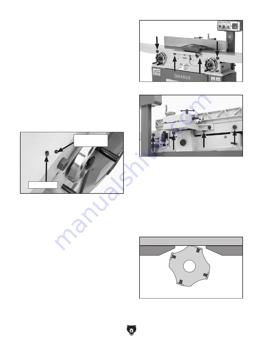
2. Remove the screw cover (see Figure 39)
covering each set screw on the outfeed table.
Note: It may help to clean the screw covers
with electrical parts cleaner. Push duct tape
firmly against the cover, then pull straight up.
Figure 40. Front eccentric bushings.
3. Loosen each set screw (see Figure 39) two
turns.
4. Place the straightedge in one of the positions
shown in
Figure 35, and adjust the table by
turning the eccentric bushings (
Figures 40 &
41) as needed with an adjustable wrench so
that the straightedge touches the cutterhead
while lying flat across the outfeed table.
Repeat this step with each of the remaining
straightedge positions as many times as nec-
essary until the outfeed table is parallel with
the cutterhead to within 0.010"-0.012".
Note: Setting the outfeed table parallel to the
cutterhead within 0.010"-0.012" will produce
high quality results. Going lower than this
number will produce minimal gain.
5. Tighten the set screws and replace the screw
covers on the outfeed table.
6. Remove each of the four screw covers on
the infeed table, and loosen the set screws
underneath.
7. Place the straightedge halfway across the
infeed table and halfway over the outfeed
table, then adjust the infeed table even with
the outfeed table, as shown in
Figure 37.
Straightedge
Outfeed Table
Infeed Table
Figure 42. Infeed and outfeed tables adjusted
even.
Figure 41. Rear eccentric bushings.
Figure 39. Screw cover and set screw location.
Screw Cover
Set Screw
(Out of View)


