


-30-
G0513X/G0514X/G0514X3 Extreme Series Bandsaw
NOTICE
Make sure that the blade teeth will not con-
tact the guide bearings when the blade is
against the rear support bearing during the
cut or the blade teeth will be ruined.
5.
Tighten the cap screw on the lateral adjust-
ment rod.
6.
Loosen the bearing rotation adjustment cap
screws.
7.
Rotate the knurled knob to position the
bearings 0.004" away from the blade.
Note:
0.004" is approximately the thickness of a
dollar bill.
8.
Tighten the cap screw to lock the blade guide
bearings in position.
9.
Repeat this procedure for the lower guides.
NOTICE
Whenever changing a blade or adjusting ten-
sion and tracking, the upper and lower blade
support bearings and guide bearings must
be properly adjusted before cutting opera-
tions.
Aligning Table
To ensure cutting accuracy when the table is first
installed, the table should be aligned so that the
miter slot is parallel to the bandsaw blade. This
procedure works best with a
3
⁄
4
" blade installed.
To align the table so the miter slot is parallel
to the bandsaw blade:
1.
Make sure that the blade is tracking prop-
erly and that it is correctly tensioned.
2.
DISCONNECT BANDSAW FROM POWER!
3.
Loosen the trunnion bolts that secure the
trunnions to the table.
4.
Place an accurate straightedge along the
blade. The straightedge should lightly touch
both the front and back of the blade.
Note:
Make sure the straightedge does not go
across a tooth.
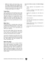
5.
Use a fine ruler to gauge the distance
between the straightedge and the miter slot.
The distance you measure should be the
same at both the front and the back of the
table (see
Figure 34
).
6.
Adjust the table as needed for proper align-
ment.
7.
Tighten the trunnion bolts.
Figure 34.
Measuring for miter slot to be parallel
with blade.
Содержание EXTREME G0513X
Страница 8: ...8 G0514X2 G0514X3 Manual Insert G0514X2 G0514X3 Main Parts...
Страница 9: ...G0514X2 G0514X3 Manual Insert 9 G0514X2 G0514X3 Fence Guides Parts...
Страница 13: ...G0514X2 G0514X3 Manual Insert 13...
Страница 14: ...14 G0514X2 G0514X3 Manual Insert...
Страница 15: ...G0514X2 G0514X3 Manual Insert 15...
Страница 16: ...16 G0514X2 G0514X3 Manual Insert...
Страница 18: ......
Страница 36: ...18 G0513X G0514X G0514X3 Extreme Series Bandsaw Hardware Recognition Chart...
Страница 72: ...54 G0513X G0514X G0514X3 Extreme Series Bandsaw G0513X Wiring Diagram G0513X Wiring Diagram...
Страница 74: ...56 G0513X G0514X G0514X3 Extreme Series Bandsaw G0514X Wiring Diagram...
Страница 76: ...58 G0513X G0514X G0514X3 Extreme Series Bandsaw G0514X3 Wiring Diagram G0514X3 Wiring Diagram...
Страница 77: ...G0513X G0514X G0514X3 Extreme Series Bandsaw 59 G0513X Main Parts...
Страница 78: ...60 G0513X G0514X G0514X3 Extreme Series Bandsaw G0513X Fence Guide Parts...
Страница 82: ...64 G0513X G0514X G0514X3 Extreme Series Bandsaw G0514X G0514X3 Main Parts...
Страница 83: ...G0513X G0514X G0514X3 Extreme Series Bandsaw 65 G0514X G0514X3 Fence Guide Parts...
Страница 89: ......
Страница 90: ......
Страница 91: ......
Страница 92: ......