background image


www.gripone.com 

2.0 Security 


During the installation of this product, it is recommended to position the motorbike in such a way that is cannot cause any injury or 

damage by falling down or moving forward or backward;  it is recommended to use the rear stand or, if necessary, the wheel lock.  

Make  sure  that  the  injection  system  is  always  turned  off  and  that  the  electrical  equipment  is  not  being  powered  during  the 

installation  of  this  product  (and,  as  well  as,  during  all  assembly  phases  indicated  in  this  manual).    When  adding  or  removing 

electrical cables or wiring to/from the motorcycle’s equipment, always be sure to remove the negative battery terminal before the 

positive  battery  terminal.    During  reassembly  phases,  connect  the  negative  terminal  last  in  order  to  avoid  short  circuiting  the 
electrical equipment. 


2.1 Recommandation 
 

DO NOT RUSH! When installing the GRIPONE control unit, make sure that the unit is protected from excessive vibrations and 

surrounding elements and that it is clamped firmly.  When you use the adhesive parts (for setting up the control unit or cables), 
make  sure  that  the  mounting  surfaces  are  clean  and  free  of  dust  or  grease  by  cleaning  them  with  degreasing  solution.  When 

positioning the wiring, make sure that the wires cannot be pinched or crushed which may cause subsequent malfunctions, clamp 

them as necessary.  For safe and professional assembly, it is recommended that you solder the connections when possible and use 

thermo-tightening  bands  to  isolate  the  various  conductors.    Place  the  hot  part  of  the  welder  on  the  ends  of  the  wires  before 

putting  them  in  contact  with  each  other.    Do  not  hesitate  to  contact  the  vendor/supplier  for  assistance  if  you  encounter  any 

difficulties  with  the  installation  of  this  device.  WARNING!    The  GRIPONE  control  unit  must  be  placed  where  the  operating 
temperature does not exceed 65°C and should be installed where it will be protected from vibrations and surrounding elements.  

Locate a flat surface on which to secure the control unit.  Do not secure the unit until the installation of all other components has 

been completed and the wiring has been secured.  


Attention 

 
The  use  of  a  traction  control  system  does  not  prevent  the  fall  caused  by  improper  use  of  the  throttle  of 
vehicle.  For  this  reason  it  is  advisable  to  test  the  functioning  of  the  system  GRIPONE  through  repeated  trials 
and  through  small  steps.  Only  after  you  had  the  right  confidence  and  you  understood  clearly  where  and  how 
the device operates on the engine and chassis, try changing the settings. 


3

.

0


Introduction to


GRIPONE CHRONO TC


GRIPONE CHRONO TC is a programmable system "stand-alone" that operate as 

traction control

anti  wheelie

launch  control

shift-up  flash

  and 

GPS

  laptimer  (GPS  module  is  optional).  All  the 

functions can work together or switched off separately.  

In  addition  the  unit  can  be  connected  to  the 

IMU

  (Inertial  Motion  Unit)  to  benefit  of                    

3D-INTELLIGENCE strategy’s. The IMU, thanks to three accelerometers is able to understand 

the  position  of  the  motorcycle,  if  it  is  accelerating  or  braking,  the  radius  of  curvature  that  the 

Содержание CHRONO TC

Страница 1: ...www gripone com Connect it to COILS INJECTORS GRIPONE CHRONO TC installation manual ENG TC TRACTION CONTROL AW ANTI WHEELIE LC LAUNCH CONTROL LT GPS LAPTIMER ...

Страница 2: ...curacy The configuration of the device requires several non trivial reflections referred to only within this manual Please note that you are installing a device on a vehicle can reach high speeds The system GRIPONE is a professional traction control system for racing use only 1 0 Included into the kit ECU Harness Kit of bracket Speed sensor ...

Страница 3: ...sible and use thermo tightening bands to isolate the various conductors Place the hot part of the welder on the ends of the wires before putting them in contact with each other Do not hesitate to contact the vendor supplier for assistance if you encounter any difficulties with the installation of this device WARNING The GRIPONE control unit must be placed where the operating temperature does not e...

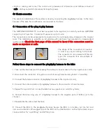
Страница 4: ... coils The shape of the connectors of injectors or coils may vary according to the bike The connector A is an example of female type The connector B is an example of male type Follow these steps to connect the plug play harness to the bike 1 Take out the fuel tank and if necessary the aribox to have access to the fuel injectors or coils 2 Disconnect the connector of injector or coil of one cylinde...

Страница 5: ...www gripone com ...

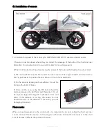
Страница 6: ...to the Y type bracket to position the rear sensor in front of rear disk bolts 4 On the sensors is designed a viewfinder It must be facing to the bolts of brake 5 Once set the sensors by the M3 bolts check the distance between the bolt head and the sensor it must be equal to approximately 2mm between 1mm and 3mm If the distance is too big the sensor can not detect the bolt If the distance is too sm...

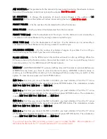
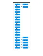
Страница 7: ...aximum and back to minimum like a loop After few seconds that you don t press any button the ECU goes back automatically on the main screen 5 1 Menu Pressing MENU button you can scroll each configuration parameter MAIN SCREEN when the unit is on and ready you can read on the LCD the following text MAP TC 00001 Controls ON The first row show the selected traction control map 00001 00002 or 00003 Th...

Страница 8: ...off the led indicator MEMORY GRIPONE CHRONO TC works as GPS lap timer GPS module is optional Before use GRIPONE as lap timer you have to clear the internal memory GRIPONE is able to keep in memory up to 200 laps When memory is full a message will shown every time you switch on the system To clear memory press one time OPTION button IMU Y 0 First time you connect the IMU to the ECU you must initial...

Страница 9: ...www gripone com ...

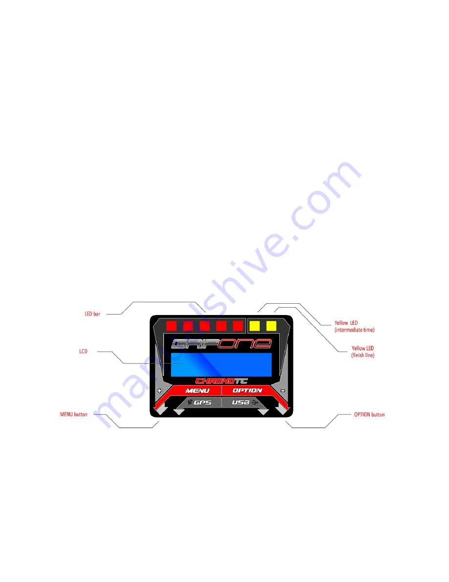
Страница 10: ...map ex map 2 to map 3 OPTION short press to switch to previous traction control map ex map 2 to map 1 MENU long press 4 sec to save GPS position of finish line OPTION long press 4 sec to save GPS position of split intermedium time Both long press 4 sec to switch ON or OFF the system 5 3 LED on ECU GRIPONE CHRONO TC has a 5 red led led bar used for show how the control strategies are working and 2 ...

Страница 11: ...without anything in the between 3 The first time you switch on the ECU after a long period for example the first time in the morning the GPS receiver will take 1 2 minutes to get the signal After the first time the GPS will take few seconds to get the signal 4 When the GPS signal is available the message GPS READY will be shown on the LCD of ECU 5 Go with the bike close to the finish line 6 Fix th...

Страница 12: ...www gripone com designed owned and made by GUBELLINI s a s di Diego Gubellini C Via Fiorentina 3508 H 40059 Medicina BO Italy P I IT03466001207 www gripone com info gripone com ...

Отзывы: