background image

SOFTWARE-TUNING

EXPERT / ADVANCED SETTINGS

ADVANCED SETTINGS

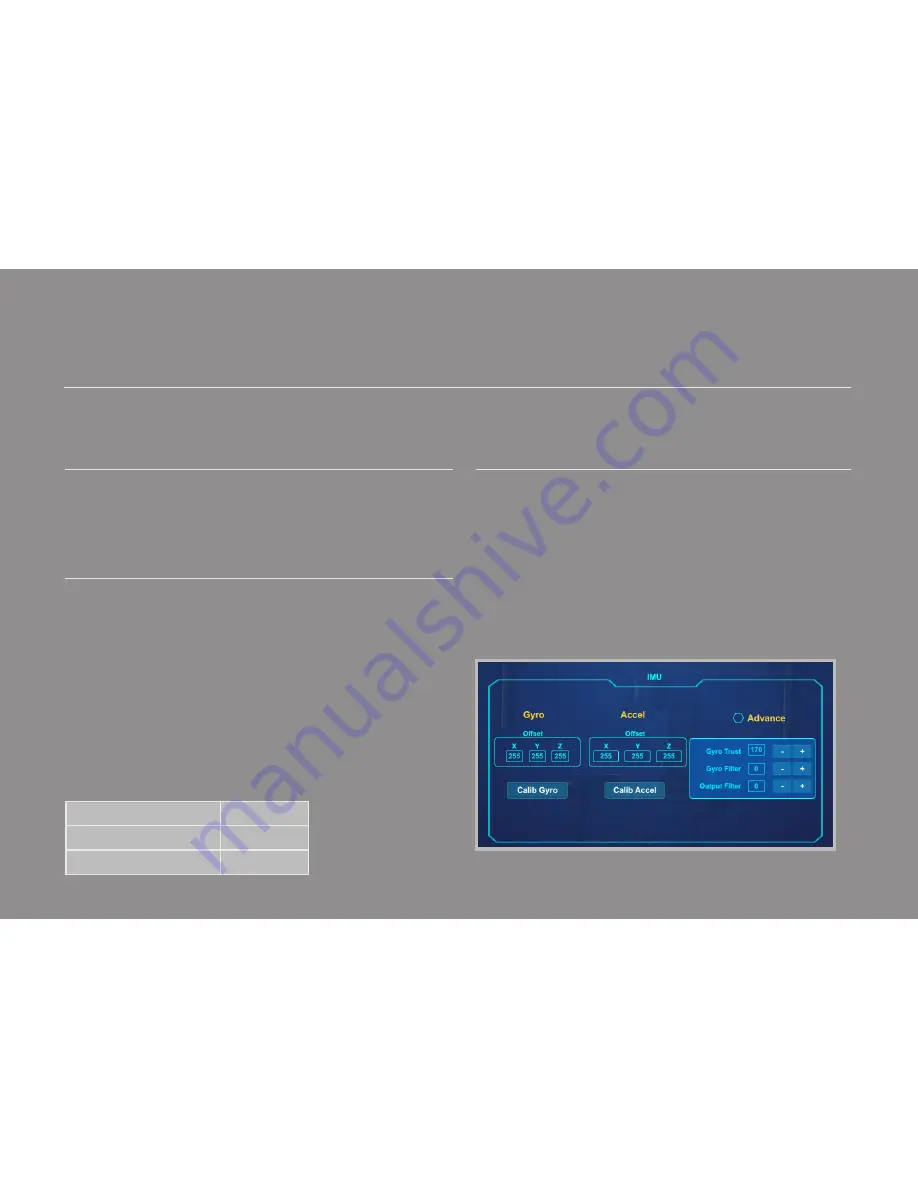
There are some advanced parameters that normally do not need to be adjusted. Leave these parameters at default settings unless they are required for troubleshooting.

GYRO TRUST:

If this value is high, attitude estimation will trust the gyro more and the acceler- 

ometer less. If Gyro Trust is too high attitude estimation is only accurate short 

term and will drift over time since gyros are subject to drift. If Gyro Trust is low, 

attitude estimation is accurate in long term but is subject to the effects of hori

-

zontal acceleration and will cause the attitude estimation to be inaccurate while 

accelerating/decelerating.

GYRO FILTER:

Defines the strength of the filter applied to to Gyro sensor output. If the gim

-

bal has oscillations that cannot be corrected by adjusting stiffness settings, you 

can use the Gyro Filter to further tune the gimbal and remove the oscillation.

If the oscillation is fast or buzzing (high frequency), try increasing Gyro Filter.

If the oscillation is slow or rocking (low frequency), try decreasing Gyro Filter.

NOTE:

 the higher the Gyro Filter the more delay you add to angle estimation of the con-

troller. Normally for lightweight camera, the inertia of camera is small therefore the rate of 

change in movement is fast, in turn it’s necessary to keep the filter low enough that angle 

estimation of the controller is not lagging compared with rate of change in movement of the 

camera. For heavy cameras the inertia of the camera is large therefore the rate of change in 

movement is slow which allows a higher Gyro Filter.

OUTPUT FILTER:

Defines the strength of the filter applied to motors output. If the gimbal has oscil

-

lations that cannot be corrected by adjusting stiffness settings, you can use the 

Output Filter to further tune the gimbal and remove the oscillation.

If the oscillation is fast or buzzing (high frequency), try increasing Output Filter.

If the oscillation is slow or rocking (low frequency), try decreasing Output Filter.

NOTE:

 the higher the Output Filter is changed, the more delay you add to the motor output. 

Normally for lightweight cameras, the inertia of the camera is small therefore the rate of change 

in movement is fast, in turn it’s necessary to keep the filter low enough so that motor output 

is not lagging compared with rate of change in movement of camera. For heavy cameras the 

inertia of the camera is large therefore the rate of change in movement is slow which allows a 

higher Output Filter. Higher filter values also results in higher stiffness settings but too much 

filter could cause low frequency vibration.

DEFAULT VALUES:

Gyro Trust

200

Gyro Filter

2

Output Filter

4

19

Содержание H3

Страница 1: ...GREMSY H3 USER MANUAL Ver 1 6 ...

Страница 2: ... in com bination with an ultra accurate IMU sensor the GREMSY H3 produces amazingly smooth footage bringing a new level of stability to even the most demanding situations The built in stand makes it extraordinarily portable compact and conve nient during transport Designed to be as light as possible the gStabi H3 can support a wide range of professional cameras and accessories with a combined weig...

Страница 3: ...ROL SBUS PPM settings JR SPEKTRUM settings JOYSTICK settings 08 SPECIFICATIONS 05 WORKING OPERATION Normal operation Inverted operation Suitcase operation 07 TROUBLESHOOTING 06 UPGRADING FIRMWARE 02 BALANCING Tilt axis front back balance Tilt axis vertical balance Roll axis balance Pan axis balance 03 SOFTWARE TUNING Stiffness tuning Auto tuning Expert advanced settings Follow mode settings Rotati...

Страница 4: ... Quick release adapter Pan motor Pan axis adjustment Battery Side handles Built in stand Tilt motor Top bar slider hotshoe Camera tray slider Tilt axis vertical adjustment Roll motor Roll axis extended adjustment 01 02 03 04 05 06 07 08 09 10 11 12 13 ...

Страница 5: ... socket on the side of the charger The charger will automatically start charging The cell 1 3 LED s will glow continuously indicating a 3 cell battery pack is being charged The charge status LED and the cell status LED will light solid red The charge status LED will glow solid green when the battery is fully charged Unplug the battery from the balance port and charge lead The battery is now ready ...

Страница 6: ...s on TILT or ROLL axis otherwises cables will get twisted and broken Slightly put one side of the battery to the battery compar ment then insert the other side Make sure the power switch is set to the OFF postition Then connect the battery lead to the power input connecter of the H3 NOTE The battery and input connecter are keyed Do not force the battery and input connector together 03 OFF ...

Страница 7: ...o be used by small children the caregiver should explain the contents of the user s manual to the children The caregiver should provide adequate supervision to insure that the device is being used as explained in the user s manual 02 WHEN CHARGING The temperature range over which the battery can be charged is10 C to 45 C Charging the battery at temperatures outside of this range may cause the batt...

Страница 8: ... release the built in stand Slide hotshoe on to the camera Put the camera on to the camera tray Follow intructions on the section BALANCING THE H3 on page 13 for more detail WARNING Be careful when you pop out the stand the legs of the stand might hit your eyes Use hand to close the 2 carbon rods then push it inside the side handles 05 ...

Страница 9: ... camera STEP 03 If the status LED is blinking green the gimbal is ready for use By default the gimbal is in Follow mode Press the Function Button one time to turn motors on Pan and tilt will hold the last orientation during turning on motor in follow mode so use your hand to position pan and tilt as your prefered orientation If the status LED is blinking red the battery is empty If the status LED ...

Страница 10: ...System Ready Lock Mode Follow Mode Remote with Lock Mode Remote with Follow Mode STATE LED STATUS DESCRIPTION 1 2 3 4 5 6 7 8 9 Solid Solid Solid Solid Solid Blink Blink Blink Blink Blink Blink Blink 10 11 12 Auto tuning in process Canlink with Lock Mode Canlink with Follow Mode ...

Страница 11: ...r methods such as using the function button or software will not take effect because the remote control signal has highest priotity and override the command The GREMSY H3 has 2 operation modes SINGLE OPERATOR using FOLLOW mode or Joystick to control the direc tion of a camera DUAL OPERATOR a second operator can use a Remote Controller SBUS SPEKTRUM or iPad Application with Motion Gesture Control T...

Страница 12: ... Mode Click on the Lock Follow icon to choose Lock Mode Follow Mode Click on the center circle icon to turn motors On Off Click on the Lock Follow icon to choose Lock Mode Follow Mode Click on the center circle icon to turn motors On Off Click on the center circle icon to turn motors On Off Click on Motors ON OFF to turn motors ON OFF USING SOFTWARE USING IPAD USING IPHONE USING ANDROID 09 ...

Страница 13: ...GETTING STARTED INSTALLING THE SOFTWARE APP Download at www gremsy com Support Software Manuals 10 ...

Страница 14: ... Manuals STEPS TO CONNECT 1 Power on the H3 2 Connect USB cable from gStabi controller to Mac PC 3 Run the gStabiSC software 4 In gStabiSC software select Serial option on connection tab 5 Select the port in the list 6 Click on the Connect button To configure and monitor data of gStabi Software Apps either USB WI FI connection is required Connect Disconnect Button Serial Port List 11 ...

Страница 15: ... the Wifi option on the Connection tab 5 Click on the Connect button ON iOS ANDROID DEVICES STEPS TO CONNECT 1 Select the wifi network named with gStabi_xxxx 2 Enter the default wifi password gremsygstabi 3 Start the gStabi Application Application will detect and connect to gStabi System automatically Wifi connection default values IP 10 10 10 254 PORT 8080 02 USING WI FI CONNECTION DEFAULT WI FI ...

Страница 16: ...3 axes that need to be precisely balanced prior to powering up the gimbal When the proper front back balance is achieved the camera will stay level when you remove your hand 1 Insert the camera to the camera tray and slightly tighten the camera using thumb screw 2 Slightly tighten the knob on the top bar to the hotshoe Gently slide the camera for ward or backward until the tilt axis remains level ...

Страница 17: ... forward and backward until the camera remains pointing upwards when released 3 Tighten the clamps and check the num ber markings on both vertical bars are the same Sometimes you may need to go back to tilt front to back balance if the vertical balance could not be achieved When the proper vertical balance is achieved you can rotate the camera in any angle and it will stay at that position 14 ...

Страница 18: ...ow the roll bar to slide left and right 2 Slide the camera left or right until roll axis remains level 3 Tighten the adjustment knob of the roll axis to lock the roll bar in position When the proper left right roll balance is achieved the camera will stay level when you remove your hand 15 ...

Страница 19: ...he back of the gimbal is pointing to the low side it means the gimbal is back heavy Slide the pan axis slider to front 2 Align pan axis parrallel with the handle bar and release Observe which way the pan axis rotates 5 Try sliding the pan axis slider to the front or back until the camera does not swing and camera will stay at any given position when released Tighten both knobs to make sure pan axi...

Страница 20: ...oscillation subsides STEP 01 TILT STIFFNESS Slowly increase this setting until you feel an oscillation in the tilt axis then reduce the setting until the oscillation subsides Make sure there is no vibration when tilting the camera up and down and when moving the handle in any orientation STEP 02 ROLL STIFFNESS Slowly increase this setting until you feel an oscillation in the roll axis then reduce ...

Страница 21: ...o find a good setting the process will take around 1 2 minutes Please turn motor on prior to starting Auto Tuning NOTE The settings found by Auto Tuning are usually good to start with however it s recommended to manually reduce stiffness if there is oscillation in a specific axis or increase stiffness in case if it is too low 18 ...

Страница 22: ... is small therefore the rate of change in movement is fast in turn it s necessary to keep the filter low enough that angle estimation of the controller is not lagging compared with rate of change in movement of the camera For heavy cameras the inertia of the camera is large therefore the rate of change in movement is slow which allows a higher Gyro Filter OUTPUT FILTER Defines the strength of the ...

Страница 23: ...m to maximum level depending on displacement between current angle and commanded angle NOTE For heavy cameras it s suggested to increase hold strength for each axis around 10 than default value If Auto power adjustment is not selected Hold strength will be fixed power level provided to corresponding axis and should be adjusted manually This option is only recommended for advanced users Gain Define...

Страница 24: ... walking or running it s recommended to set the tilt window to 20 30 degrees or have Tilt lock selected to reduce walking motion in the footage When riding a horse or running it s recommended to set the pan window to around 20 30 degrees because you can t hold the gimbal still The most widely used mode in handheld application is follow mode where the gimbal operator controls pan and tilt of the ca...

Страница 25: ... in 0 1 degree unit and is only applicable when there is no remote control signal since remote control will override the tilt angle ROLL OFFSET Set the roll offset in 0 1 degree unit is only applicable when there is no remote control signal since remote control will override the roll angle This is useful to fine trim the horizon Travel of each axis can be limited using UP LIMIT and DOWN LIMIT 22 ...

Страница 26: ...ro Offset X Y Z will change to a new value depending on the temperature ACCELEROMETER CALIBRATION Do not use this function please contact Gremsy Support Engineers Accelerometer sensor was calibrated properly at factory to achieve accurate horizon level with special and precise equipment Users do not need to do this unless it s required for troubleshooting The IMU sensor used in the H3 is a combina...

Страница 27: ...ng axis will depend on how far the stick position is from the neutral position It is recommended that TILT and PAN channels should be set to speed mode ANGLE MODE when angle mode is selected the corresponding axis will move to the angle set by current stick knob position It s recommended ROLL channel should be set to angle mode Simply connect SBUS PPM wires from the receiver to the SBUS PPM connec...

Страница 28: ...an example of channel assignment to the Futaba T8FG Assign MODE channel first then follow the order above because MODE channel is used to change operating modes of the gimbal and should be assigned with a 3 position switch as follows Switch at position 1 FOLLOW MODE MOTORS ON Switch at position 2 LOCK MODE MOTORS ON Switch at position 3 MOTORS OFF SBUS PPM SETTINGS Pos 01 Pos 02 Pos 03 MODE channe...

Страница 29: ...ic cover and connect satellite receiver to the correct connector as shown in the picture Make sure satellite receiver is already bound to the transmitter RED led is solid Choose 10 bit or 11 bit type resolution on the software and assign proper channels as per SBUS settings SATELLITE RECEIVER 26 ...

Страница 30: ...ill smoothing are adjustable via software as below SMOOTH increasing this number will smooth out the movement of the corresponding axis but will also cause a delay SPEED increasing this number will increase the speed of movement in the correspond ing axis Install joystick bracket using 2xM3 to hold the joystick in place Connect joystick cable on the joystick connec tor and on the pan bracket 27 ...

Страница 31: ...OPERATION WORKING OPERATION era is underslung When the gimbal is in follow mode and normal Moreover you can set the gimbal into Inverted you to shoot higher and or at eye level along a narrow space gimbal into lock mode then move the handle to 28 ...

Страница 32: ...re at www gremsy com Support Software Manuals HOW TO UPGRADE 1 Power on the H3 2 Connect USB cable from gStabi controller to Mac PC 3 Run the gStabiSC software 4 In gStabiSC software select Serial option on connection tab 5 Select the port in the list 6 Click on the Connect button 7 Go to Upgrade tab 8 Browse to firmware file from your computer 9 Click Upgrade button The process will take about 2 ...

Страница 33: ... be drifting Gyro sensor is drifting too much Re calibrate gyro gStabi has ossilation in one or more axes Stiffness setting is too high Reduce stiffness Quick clamp thumbscrew top bar nut is not tightented Check tightening If necessary adjust the clamp tension with a hex wrench Camera mounting is not stiff enough Check camera mounting Filters settings are incorrect Gyro and output filter should on...

Страница 34: ...X H 90mm x 162mm x 150mm Construction Aluminum Carbon Fiber Input Voltage 12 6 VDC Battery 3S 3400mAh Li ion weight 143 5 g Connection USB Wifi Payload 1 7 kgs 3 7 lbs OS Platform Supported Windows Mac iOS Android Single Operator Follow Mode Thumb Joystick Dual Operator SBUS Spektrum PPM Pan Range 360 degree continuous Tilt Range 90 degree Roll Range 45 degree Encoder Resolution 0 005 degree 31 ...

Страница 35: ...gremsy com ...

Отзывы: