background image

910FS Splicer

Greenlee / A Textron Company

4455 Boeing Dr. • Rockford, IL 61109-2988 USA • 815-397-7070

12

Turning Splicer ON

Press and hold   until the LED on the keypad turns ON (green color).

?

The “Ready” screen is displayed after all the motors reset to their initial positions.

The power source type is automatically identified. If the battery is used, the remaining 
battery capacity is displayed.

Splice Mode

Use SM splice mode for standard SM fiber (ITU-TG.652) splicing. It performs splices in 
9 seconds and is the quickest mode for SM fiber splicing.

Use AUTO splice mode if fiber type is not identified. Splice takes 2 seconds longer but it 
covers most conventional fiber splicing for the following reasons:

•  AUTO mode first identifies fiber type by analyzing fiber profile, and the splicing 

condition is chosen for the type of fiber. The types of fibers covered by AUTO are 
all the conventional fibers, such as SMF (G652), BIF (G657), NZDSF (G655), MMF 
(G651), etc. AUTO mode takes longer than the SM processes but is recommended 
in cases where the fiber type is not positively identified or if the user is new to fusion 
splicing.

•  AUTO mode uses an automatic arc calibration function, which monitors the splicing 

process and ensures adequate arc power for the splice.

Automatic Arc Calibration Function

When the automatic ARC calibration function is enabled the previous splice’s ARC 
power is used. If the ambient conditions or type of fiber has changed an ARC calibration 
may be required. The automatic arc calibration function works in AUTO modes only. It 
is not active in the standard splice modes. When using those modes, performing arc 
calibration before splicing is strongly recommended.

Содержание 910FS

Страница 1: ...rstand all of the instructions and safety information in this manual before operating or servicing this tool Register this product at www greenlee com 52063481 REV 5 2017 Greenlee Textron Inc 10 17 91...

Страница 2: ...15 Heating Protection Sleeve 17 Cooling Tray 17 Splice on Connectors 17 Carrying Case with Work Table 18 Upgrading Software 19 Button Functions 19 Appendixes 19 Section 3 Menu Operation 20 Splice Mod...

Страница 3: ...ist 910FS fusion splicer 250 micron adapter pair 900 micron adapter pair SC LC splice on connector adapter Spare electrodes one pair AC adapter power supply with line cord Battery pack installed in 91...

Страница 4: ...gases or fumes Do Not Remove Instrument Cover Do not remove the cover of the unit for any reason It contains no user serviceable parts SAFETY ALERT SYMBOL This symbol is used to call your attention t...

Страница 5: ...injury or death Electric shock hazard Use only AC adapter or battery charger designed for this splicer Using an improper AC power source could cause fuming electric shock or equipment damage Do not d...

Страница 6: ...ic shock or equipment damage This tool uses a three prong core AC power cord that contains an earthed ground safety mechanism This tool must be grounded Use only the supplied power cord Never use a tw...

Страница 7: ...reenlee service center for repair Failure to observe these warnings could result in severe injury or death Battery safety Do not allow anything to contact the battery terminals Do not immerse batterie...

Страница 8: ...d may damage the unit Follow these instructions for handling electrodes Use only specified electrodes Set new electrodes in correct position Replace electrodes as a pair Failure to observe this precau...

Страница 9: ...lee A Textron Company 4455 Boeing Dr Rockford IL 61109 2988 USA 815 397 7070 9 Section 1 Identification Components of Splicer Keypads LCD Wind Protector Tube Heater Cooling Tray RS 232 Port USB Port B...

Страница 10: ...Splicer Greenlee A Textron Company 4455 Boeing Dr Rockford IL 61109 2988 USA 815 397 7070 10 Top View V groove Guide Groove Electrode Cover Wind Protector Mirror Fiber Adapter Fiber Adapter Electrode...

Страница 11: ...e battery compartment until it clicks into place Removing the Battery Turn off the splicer Push the release button located on the side of the splicer body and remove the battery Two Methods of Checkin...

Страница 12: ...ype by analyzing fiber profile and the splicing condition is chosen for the type of fiber The types of fibers covered by AUTO are all the conventional fibers such as SMF G652 BIF G657 NZDSF G655 MMF G...

Страница 13: ...ttempt to clean the fiber on the splice on connector Follow the instructions supplied with the splice on connectors Clean optical fiber with alcohol soaked gauze or lint free tissue Dust particulates...

Страница 14: ...r with alcohol soaked 99 or greater gauze or lint free tissue Fiber Cleaving Do not let the fiber end face touch anything Place the fiber into the universal adapter and insert the adapter into the 910...

Страница 15: ...e used for visual inspection If observed remove the fiber from the splicer and repeat fiber preparation These fiber cleave defects may cause a faulty splice Chip Lip Incline After fiber inspection the...

Страница 16: ...timate and splice check are performed again Splice loss may be worsened in some cases by additional arc discharges re arcs Additional arc discharge can be set to disabled or limited to the number of a...

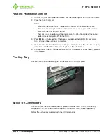
Страница 17: ...Use heater profile 1 for the SOC 3 Press to start tube heating The beeper sounds and the HEAT LED red color turns off when tube heating is completed 4 Open the tube heater lids and remove the protect...

Страница 18: ...397 7070 18 Carrying Case with Work Table The top cover of the carrying case can be used as a work table Place the tray mounting attachment on the top of the case and mount the fusion splicer on top...

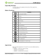
Страница 19: ...F Menu key Enter key Return Exit key Left key Right key Help key Up key Bright key for LCD Down key Dark key for LCD Start Stop heating protection Re calibrates arc power Resets the motor position Sta...

Страница 20: ...y 4455 Boeing Dr Rockford IL 61109 2988 USA 815 397 7070 20 Section 3 Menu Operation Press to enter the splicer menu There are six main menus 1 Splice Mode Menu S Mode 2 Heater Mode Menu H Mode 3 Main...

Страница 21: ...MFD is 7 to 9 m at wavelength near 1550 nm User can edit all parameters of this splice mode such as prefuse power prefuse time arc power arc time align proof test etc The manual splicing operation is...

Страница 22: ...to select the splice mode Then press 8 to confirm Note 1 AUTO SM NZ DS MM mode is recommended for splicing in most cases In this mode the splicer automatically adjusts splice parameters according to...

Страница 23: ...egrees Cleaning Arc Set or disable the duration of the cleaning arc Gap Increase the gap if the fibers are soft and melt too easily Decrease the gap if the fibers are hard to melt Gap Set Set the gap...

Страница 24: ...Prefuse Power G Arc1 Power H Arc2 Power I Arc2 ON Time J Arc2 OFF Time Note Not all settings are available in the AUTO modes This is a general guideline for the user to control the fusion settings Eve...

Страница 25: ...q to highlight the desired heater mode Then press 8 to confirm Select the heater mode most suitable for the protection sleeve to be used Press p or q to select a heater mode Then press 8 to confirm 2...

Страница 26: ...name Mode Title1 Enter the heater mode setting name Mode Title2 Enter the alternate heater mode setting name Heat Time Enter the heater duration Heater Control Enter the splice protector size as Long...

Страница 27: ...just screen replace electrodes and stabilize electrodes Arc Calibration Used to calibrate arc function to obtain the best splicing results when a splicing session is first started or if the splicing e...

Страница 28: ...9 pure IPA Do not touch the electrode surface with your fingers Now is a good time to clean the objective lens while the electrodes are not in the way 4 Re install the electrodes into the splicer 5 Pe...

Страница 29: ...een boundaries 1 Prepare and load left and right fibers 2 Press 8 and then press p and q to switch between X and Y screen views 3 Press p and q to adjust the fiber positions 4 Press 8 to confirm modif...

Страница 30: ...e arc display is not a uniform light pattern 1 Prepare and load left and right fibers 2 Press 8 and wait for the splicer to automatically stabilize the electrodes Splice Set Splice setting options inc...

Страница 31: ...910FS stores up to 5000 splicing results which can be downloaded via the USB port Navigate to the Data Save icon and press 8 to access Splice Memory The Splice Memory function allows the user to disp...

Страница 32: ...ice Memory menu to delete splice results Use t and u to switch between Start and End number of splice results Use p and q to change value Press 8 to confirm and press 9 to exit Format Memory The Forma...

Страница 33: ...L 61109 2988 USA 815 397 7070 33 Maintenance INFO The Maintenance INFO function allows the user to check total fusion count software version and serial number information Set This menu is used to set...

Страница 34: ...ford IL 61109 2988 USA 815 397 7070 34 Beep Switch The Beep Switch function allows the user to enable or disable the splicer beeper Screen Direction The Screen Direction function allows the user to ch...

Страница 35: ...adjustable The LED indicator turns on after Power Save is enabled Press any key to turn the LCD monitor back on The splicer can also be set to automatically turn off after a certain period of time wit...

Страница 36: ...e and time information Press t or u to select the item to adjust and press p or q to increase or decrease the value Press 8 to confirm Sensor Value Displays pressure XXX Hpa and temperature XXX C Load...

Страница 37: ...cer is restarted the password interface is displayed Customer can use the password to unlock To cancel the password function select Set password and then select FINISH input nothing for password For s...

Страница 38: ...plice Results 5000 results Tension Test 2 N Fiber Display Magnification 240X Tube Heating Mode 20 preset and user definable modes adjustable 0 240 seconds Attenuator Mode 0 1 to 15 dB Electrode Life 3...

Страница 39: ...Check if fiber cleaver is clean and in good condition Prefuse power too low or prefuse time too short Increase Prefuse Power and or Prefuse Time MFD mismatch Arc power too low Increase Arc Power and o...

Страница 40: ...ap Line Some arc parameters not adequate Adjust Prefuse Power Prefuse Time or Overlap Note A vertical line sometimes appears at the spice point when MM fibers or dissimilar fibers different diameters...

Страница 41: ...fibers i e MM fiber Set Focus to Edge to splice indistinct core fibers i e MM fiber To splice distinct core fibers enter Auto or the correct focus value Left Right fiber X Y set error The fiber is not...

Страница 42: ...o do the arc calibration Do arc calibration Electrodes are oxidized Clean electrodes or replace with a new pair Lenses are dirty Clean lenses FIBER_PUSH_ERR Fiber is not in V groove Replace fiber and...

Страница 43: ...p causes poor fiber movement during fiber adjusting Clean them periodically Dust or dirt is on the lens or mirror If dust or dirt exists clean the lenses or mirrors Bad electrode condition Replace the...

Страница 44: ...he V groove with a clean dry lint free cotton swab V grooves Cleaning Swab V grooves Cleaved Fiber Figure 1 Figure 2 If the contaminants in the V groove cannot be removed with an alcohol impregnated l...

Страница 45: ...e surfaces of the objective lenses become dirty normal observation of the core position may be incorrect resulting in higher splice loss or poor splicer operation Therefore clean both of them at regul...

Страница 46: ...o the electrodes General Fusion Splicer Cleaning recommended daily Use the cleaning brush only to clean debris from general working area never on the lenses V grooves or mirrors Periodically clean the...

Страница 47: ...has a pre programmed splicing profile in the 910FS Use this profile for splicing 4 If there is not an exact matching splice profile use the AUTO mode splicing profile 5 Splice a fiber pigtail with a...

Страница 48: ...r meter Refer to Figure 4 5 Obtain an approximately 10 m length of fiber same as the field fiber 6 Determine if this fiber type has a pre programmed splicing profile in the 910FS Use this profile for...

Страница 49: ...en the 27 mm mini splice protective sleeve over the 900 m field fiber Use the 910CL to cleave the field fiber Insert the fiber adapter with the cleaved fiber into the left hand side of the 910FS fusio...

Страница 50: ...n fiber adapter Note Remove the extended dust cap before initiating the fusion splice Figure 6 6 Perform the fusion splice as described in the fusion splicer manufacturer s instructions 7 Once the fus...

Страница 51: ...FSM11 S M FSM 17S FSM 18S Type 25e U S M S122 A C M IFS10 CA3 FSM 19S Type 39FH S121 A M IFS15 FSM 60 S R Type 46 S123 C M FSM 70 S R Type 66 S153 Quantum Q101 CA S178A Compatible fiberTOOLS SOCs All...

Страница 52: ...these products will be free from defects in workmanship and material for one year This war ranty is subject to the same terms and conditions contained in Greenlee Textron Inc s standard one year limit...

Отзывы: