10
o o
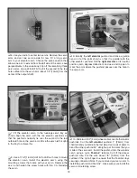
15 . Use two #2 x 1/2" [13mm] sheet-metal screws to
attach the control horn to the aileron .
Important: Remove
the screws and harden the holes with thin CA . Reinstall
the screws .
o
16 . Repeat steps 13 through 15 for the other wing .
o
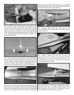
17 . Locate the two 2-56 x 12" [305mm] threaded aileron
pushrods, two nylon clevises, and two silicone clevis retainers .
Slide a silicone retainer on each pushrod and thread each
clevis on so that at least 1/16" [1 .6mm] of thread protrudes
past the clevis barrel .
o
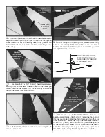
18 . Center your aileron servos using your radio . Place
a piece of tape across the inboard edge of the ailerons to
hold them in the neutral position during this step . Attach
each pushrod to the outermost hole of each aileron control
horn . Extend the pushrod forward and line it up with the
servo arm hole . Mark the pushrod at the hole .
o
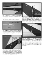
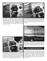
19 . Bend the pushrod 90° at the mark that you made .
Connect the pushrod to the outermost hole in the servo
arm . Install a
nylon FasLink
™
and cut the excess end of the
pushrod . If you use a Dremel tool with a cutoff wheel, remove
the nylon FasLink
™
before cutting the wire to avoid melting
the plastic . Do this for both wings .
o
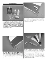
20 . With your radio still on, adjust the length of each
pushrod until the control surface is neutral (zero control
throw) . You may do this by removing the clevis from the
control horn and rotating it to adjust the length of the pushrod .
Move the ailerons through their full rate of travel and check
for any interference between the linkages and the servo bay
covers . If necessary, trim away the opening in the servo bay
cover . When you’re done, slide the silicone clevis retainer
into position .
Содержание Z-526 ZLIN krobat
Страница 40: ......


