background image

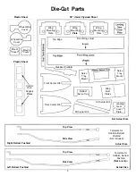
Die-Cut  Parts

Plastic Sheet 

1/8" (3mm) Plywood Sheet

Wheel Well

Cover

Wing

Mounting

Plate

Wing

Mounting

Plate

Wing

Mounting

Plate

Wheel Well

Cover

Mount

Cover

Mount

Cover

Plastic Sheet

Control

Horn

Support

Plates

Front Center Rib

Front  Center Rib

Aft Center Rib

Aft Center Rib

Landing

Gear

Cover

Plate

Wing

Bolt

Plates

Retract

Servo Tray

Servo

Tray

Mount

Servo

Tray

Mount

Stabilizer Platform

(Angle)

Front Wing Joiner

Top Edge

Not Actual Size

Top View

Side View

Right Retract Pushrod

Template for

Hobbico Retract

Pushrod

(Not  Included)

Actual  Size

Top View

Side View

Left  Retract Pushrod

5

Template for

Hobbico  Retract

Pushrod

(Not Included)

Actual  Size

Содержание Ultra-Sport 40 ARF

Страница 1: ...nal assembly or material used for final assembly no liability shall be assumed nor accepted for any damage resulting from the use by the user of the final user assembled product By the act of using the user assembled product the user accepts all resulting liability If the buyer is not prepared to accept the liability associated with the use of this product they are advised to return this kit immed...

Страница 2: ...NSTALLATION 4 stroke 13 MOUNT THE WING 14 HORIZONTAL STABILIZER 15 VERTICAL STABILIZER 16 TAIL GEAR 16 GLUING THE HINGES 17 STABILIZER SUPPORT BRACES 18 RADIO INSTALLATION 19 PUSHRODS 20 CONTROL SURFACE LINKAGE 21 THROTTLE LINKAGE 21 RECEIVER INSTALLATION 22 FUEL TANK 23 FINAL ASSEMBLY 24 CONTROLTHROWS 25 BALANCE THE PLANE LATERALLY 25 Metric Conversion Chart Inches x 25 4 mm conversion factor 1 6...

Страница 3: ...about building or flying this airplane please call us at 217 398 8970 and we ll be glad to help Please find the kit identification number on the end of the carton and have it ready when calling The Great Planes Ultra Sport 40 ARF is like the Ultra Sport 40 kit This almost ready to fly version is one of the easiest flying most aerobatic aircraft ever designed It combines the design expertise and hi...

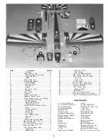
Страница 4: ... Disc 2 40 Rubber Plug 1 41 Aluminum Tube 2 42 Fuel Tubing 1 43 6 32 x 3 4 Machine Screw 4 44 Main Landing Gear Strut R 1 45 Tank Plug 3 x 18mm S T Screw 1 46 Tail Gear 1 47 Swivel Clevis 2 48 Wing Dowel 1 49 6 x 3 4 Sheet Metal Screw 4 50 2 x 3 8 Sheet Metal Screw 12 51 5 32 Wheel Collar 4 52 3 32 Wheel Collar 2 53 Aluminum Spacer 2 54 2 Washer 4 55 2 56 x 5 8 Machine Screw 4 56 1 4 20 Nylon Wing...

Страница 5: ...r Rib Front Center Rib Aft Center Rib Aft Center Rib Landing Gear Cover Plate Wing Bolt Plates Retract Servo Tray Servo Tray Mount Servo Tray Mount Stabilizer Platform Angle Front Wing Joiner Top Edge Not Actual Size Top View Side View Right Retract Pushrod Template for Hobbico Retract Pushrod Not Included Actual Size Top View Side View Left Retract Pushrod 5 Template for Hobbico Retract Pushrod N...

Страница 6: ... joiners into both wing halves A snug fit is desirable If the joiners do not fit properly lightly sand the excess epoxy and uneven surface joints from the joiner edges and sides Note The plywood and balsa wing joiners have a slight dihedral angle on one edge This angle should be on the bottom of the wing 2 Carefully glue the plywood center ribs and wing joiners together using 6 minute epoxy The pl...

Страница 7: ...he precut area from the front center rib before gluing Carefully glue the plywood center ribs and wing joiner together using 6 minute epoxy The plywood joiner has a slight angle on one edge Place these angles adjacent with each other Use clothespins to clamp the joiners and ribs together Remove the excess epoxy on the edge of the ribs and joiner using a paper towel and rubbing alcohol Modify the W...

Страница 8: ...11 Option A if retracts are being installed Continue on page 10 Assemble the Fixed Landing Gear 1 Place the landing gear mounting block between the U bend on the top portion of the main landing gear strut Secure the Mounting Blocks Join the Wing 2 Using a pen place marks on the mounting blocks 7 Trial fit the two wing halves together The wing halves should seat together without any gaps and the fr...

Страница 9: ...n the wing Install the Wheel Well Covers 5 Locate and glue the two white plastic retract wheel 7 Using 6 minute epoxy glue the plywood wing bolt plates to the bottom of the wing aligned with the trailing edge Prepare the Wing Fairing 8 Individually place the top and bottom plastic wing fairings on the wing and lightly trace its outline onto the wing well covers in place using medium CA Mount the W...

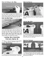
Страница 10: ...om the dowel using a paper towel and rubbing alcohol Apply the foam rubber seal to the front edge of the wing fairing It will help prevent exhaust residue from leaking into the fuselage Landing Gear Assembly Retracts Option B Skip Steps 1 13 Option B if fixed gear has been installed Continue with Aileron Assembly on page 12 Retract Modification 1 Insert the retract into the wing with the main land...

Страница 11: ... wing and lightly trace its outline Connect the Retract Linkage using threaded ball links Important The retract pushrods and retracts must be adjusted so the retracts lock in both the up and down positions 7 The linkages in the photograph have been made by Sand the Fairing and Wing 8 Secure the retract mechanism into the wing using the 11 Use medium grit sandpaper to lightly roughen the four 4 x 1...

Страница 12: ... the excess epoxy from the dowel using a paper towel and rubbing alcohol Aileron Assembly 1 Trial fit the servo into the servo tray Locate the plywood servo tray mounting blocks and glue them into the aileron servo tray opening using 6 minute epoxy The tray should be flush with the top of the wing joiners installed earlier in Step 6 Page 7 aileron torque rods until approximately 1 8 of threaded ro...

Страница 13: ... 16 from the firewall on all two cycle engines Trial fit the cowling and spinner and strive for approximately 3 32 clearance between the spinner backplate and the cowling If your engine includes a template tape the template on the mount and mark the mounting holes If your engine does not include a template place the engine on the mount and make a mark through the lug holes Drill a hole using a 7 6...

Страница 14: ... prevent exhaust residue from entering the fuselage Mark the Wing 4 Insert the nylon wing bolts from the underneath side Install the Blind Nuts 2 Install the blind nuts into the holes from the bottom side of the mounting plate Gently press the blind nuts into place with pliers or a vise The holes may need to be enlarged slightly with a 5 16 drill bit Glue the blind nuts into place with a drop of C...

Страница 15: ...m if necessary to obtain a proper fit Use 6 minute epoxy to glue the platform into place Remove any excess epoxy that remains on the top of the platform as well as on the outside of the fuselage using rubbing alcohol and a paper towel After the epoxy has cured attach the wing then place the horizontal stabilizer on the platform and check to see if the horizontal stabilizer is level with the wing b...

Страница 16: ...ical stabilizer Pin the vertical stabilizer in place and keep checking its alignment by measuring and sighting until the epoxy sets up 2 Locate the plastic vertical stabilizer fairing and lightly sand the underneath side of the fairing Slide the fairing over the vertical stab and lightly trace its outline onto the fuselage Remove the fairing Lightly sand the fuselage on the inside of the line Usin...

Страница 17: ...s enlarge the slot in the leading edge of the rudder to provide plenty of clearance for the tail gear wire Clean the tail gear wire off with rubbing alcohol Note The hinge material supplied with this kit consists of a 3 layer lamination of mylar and polyester Properly installed this type of hinge provides the best combination of strength durability and ease of installation We trust even our best s...

Страница 18: ...udder leaving a 1 32 gap between the rudder and fin It is best to leave a very slight gap rather than closing it up tight to help prevent the CA from wicking along the hinge line Make sure the rudder will deflect to the recommended throws without binding Remove the rudder and insert a small pin through the center of each hinge This pin will keep the hinge centered while installing the rudder Inser...

Страница 19: ...the wire used in the switch to allow the wire to be routed through the switch as shown in the photograph above Refer to the manufacturer s manual for more detailed information Notice the location and orientation of each servo as well as the switch location 2 Install the three servos from your radio system Connect Brace to the Stabilizer 2 Drill a 5 64 hole through the horizontal stabilizer at the ...

Страница 20: ...e Tubes Glue the Guide Tubes In Place 4 Remove a small portion of the fuselage former using a hobby knife or round file The guide tube should fit into the former flush to the edge Do not remove any more former than necessary or it will be weakened Use medium CA to glue the guide tubes into place 2 Apply masking tape to the fuselage next to the guide tubes to protect the fuselage skin while cutting...

Страница 21: ...os centered mark the pushrods Cut the rods 1 4 past the mark and make an L bend at the mark Place the L bend into the fourth or outermost hole of the servo arm It may be necessary to enlarge the servo arm holes with a 5 64 drill bit Note An alternate technique to make pushrod connections would be with the use of GP Screw Lock Pushrod Connectors for easy adjustments Correct Incorrect Connect the Co...

Страница 22: ...hrod at the mark and insert it into the servo arm securing it with a pushrod keeper Receiver Installation Install Receiver and Battery 1 Wrap the radio receiver and battery in protective foam Using 64 rubber bands secure the receiver and battery in the radio compartment There are four radio hold down tabs in the radio compartment to attach the rubber bands to Connect the Throttle Linkage 3 4 strok...

Страница 23: ...eing careful not to kink the tube bend one end of the tube in a 90 angle It may be helpful to find a rigid object that can be used as a form to bend the tube around Leave 1 1 2 of straight tube at one end so it can easily be inserted through the tank plug Assemble the Tank Plug 2 Locate the two plastic plug discs Push the aluminum tubes through the smaller stopper disc and the back of the rubber p...

Страница 24: ...etal screws Mark the screw location as shown in the photograph and drill two holes on each side of the fuselage using a 1 16 drill bit Enlarge the holes in the cowling only to 3 32 Mount the Prop and Spinner 4 Place the spinner backplate onto the engine shaft followed by the propeller Secure the propeller in place with the engine driver washer Snap the spinner into place onto the backplate Check t...

Страница 25: ...ontrol Surface Movements Elevator moves UP Riant aileron moves UP and Left aileron moves DOWN Rudder moves LEFT Carburetor Wide Open 1 Make sure the control surfaces move in the proper direction as illustrated in the following sketches 1 Accurately mark the balance point on the top of the wing on both sides of the fairing The balance point is located approximately 4 inches back from the leading ed...

Страница 26: ...fore do not run the engine in a closed room or garage Get help from an experienced pilot when learning to operate engines Use safety glasses when starting or running engines Do not run the engine in an area of loose gravel or sand as the propeller may throw such material in your face or eyes Keep your face and body as well as all spectators away from the plane of rotation of the propeller as you s...

Страница 27: ... AMA number on or in the model Note This does not apply to models flown indoors 9 I will not operate models with pyrotechnics any device that explodes burns or propels a projectile of any kind including but not limited to rockets explosive bombs dropped from models smoke bombs all explosive gases such as hydrogen filled balloons ground mounted devices launching a projectile CAUTION THIS APPLIES TO...

Страница 28: ...ht line Enjoy thrilling maneuverability and dramatic WWII fighter styling in an ARF design The Great Planes P 51D Mustang ARF is 90 prebuilt with all wood construction It features an advanced composite covering with color matched plastic parts authentic markings and even comes with a pilot figure Great Planes recreates Britain s most famous WWII fighter with the Spitfire ARF This top quality semi ...

Страница 29: ...maneuver entry can mislead you The thrust adjustments are a real pain to make On most models it means taking the engine out adding shims then reassembling the whole thing Don t take shortcuts Don t try to proceed with the other adjustments until you have the thrust line and or C G correct They are the basis upon which all other trim settings are made Also while you have landed take the time to cra...

Страница 30: ...NTERING random maneuvers level flight Tx trims are centered CONTROL Random maneuvers A Too sensitive jerky If A change linkages to THROWS controls reduce throws B Not sufficient control If B increase throws ENGINE From straight flight A Aircraft continues level If A trim is okay THRUST chop throttle quickly path for short distance ANGLE B Plane pitches nose up If B decrease downthrust C Plane pitc...

Страница 31: ... LINE ELEVATOR THROW GAUGE Ultra Sport 40 ARF HINGE LINE AILERON THROW GAUGE Ultra Sport 40 ARF HINGE LINE RUDDER THROW GAUGE Ultra Sport 40 ARF DRILL 3 32 PILOT HOLES 8 PLACES MAIN LANDING GEAR DRILL TEMPLATE ...

Отзывы: