


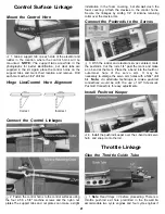


Control Surface Linkage
Mount the Control Horn
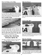
1. Glue a support tab on each side of the elevator and
rudder in the location where the control horns will be
mounted. NOTE: The support tabs are white in the
photographs for better identification, but clear tabs are
supplied in the kit. Again place the control horns on the
support tabs and mark their location and remove. Drill
each mark with a 3/32" drill bit.
Hinge Line/Control Horn Alignment
indentation in the foam covering, but do not crush the
foam covering. Attach the clevises to the control horns.
Secure the linkages by sliding 1/4" of silicone retaining
collar over the clevis arms.
Connect the Pushrods to the Servos
3. With the rudder and elevator servos centered, mark
the pushrods. Cut the rods 1/4" past the mark and make
an L-bend at the mark. Place the L-bend into the fourth or
outermost hole of the servo arm. It may be
necessary to enlarge the servo arm holes with a 5/64" drill
bit. Note: An alternate technique to make pushrod
connections would be with the use of GP Screw-Lock
Pushrod Connectors for easy adjustments.
Correct Incorrect
Connect the Control Linkages
2. Fasten the control horns to the control surfaces using
Install Pushrod Keeper
4. Install the pushrod keeper over the L-bend and servo
horn, and snap it onto the rod.
Throttle Linkage
Glue the Throttle Guide Tube
1. Note: Read Steps 1-3 before proceeding. There is a
the four 2-56 x 5/8" machine screws and the nylon nut
plates.The support tabs and nut plates can make a slight
throttle pushrod exit hole predrilled in the firewall to
accommodate two cycle engines and four cycle engines if
21


