background image

18

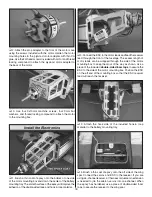
 2. Attach the prop adapter to the front of the motor case 

using the screws included with the motor. Harden the motor 
mounting holes in the plywood motor adapter with thin CA 
glue. Use the fl at head screws included with motor and thread 
locking compound to attach the plywood motor adapter to 
the back of the motor.

 3. Use four 3x10mm machine screws, four 3mm fl at 

washers, and thread locking compound to attach the motor 
to the mounting box.

Install the Electronics

 1. Brush a thin coat of epoxy onto the bottom of one side 

of the motor mounting box and down the center of the battery 
mounting tray. The smooth surface of the epoxy will improve the 
adhesion of the double-sided tape and hook & loop material.

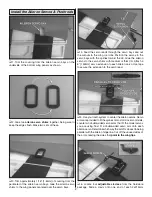
 2. Connect the ESC to the motor leads and feed the receiver 

lead through the front of the fuselage. The excess length of 
motor leads can be wrapped through the side of the motor 
mounting box to keep them out of the way as shown. Use a 
piece of the included 

double-sided foam tape

 to secure the 

ESC to the side of the motor mounting box. Position the ESC 
on the aft end of the mounting box so that the ESC receiver 
lead will reach the receiver. 

 3. Attach the hook side of the included hook & loop 

material to the battery mounting tray.

 4. Brush a thin coat of epoxy onto the aft side of the wing 

spar. Connect the servos and ESC to the receiver. If you are 
using a 4-channel receiver, a Y-harness or dual servo extension 
is needed to join the aileron servos into one channel. When 
the epoxy has hardened, use a piece of double-sided foam 
tape to secure the receiver to the wing spar.

Содержание Ultimate Biplane EP ARF

Страница 1: ...used condition to the place of purchase To make a warranty claim send the defective part or item to Hobby Services at the address below Hobby Services 3002 N Apollo Dr Suite 1 Champaign IL 61822 USA I...

Страница 2: ...Ultimate Biplane 1 60 ARF has been carried down to the Ultimate EP For the latest technical updates or manual corrections to the Ultimate Biplane EP visit the Great Planes web site at www greatplanes...

Страница 3: ...bs in your area whose membership includes experienced pilots 8 While this kit has been flight tested to exceed normal use if the plane will be used for extremely high stress flying such as racing or i...

Страница 4: ...820 Battery Pack Charger The Ultimate Biplane EP ARF has been tested with 11 1V LiPo packs ranging from 1250mAh to 2100mAh Order numbers are provided for packs of this size The lighter 1250mAh pack is...

Страница 5: ...dealer or mail order company To locate a hobby dealer visit the Great Planes web site at www greatplanes com Choose Where to Buy at the bottom of the menu on the left side of the page Follow the inst...

Страница 6: ...written in the Kit Contents list Great Planes Product Support 3002 N Apollo Drive Suite 1 Champaign IL 61822 Telephone 217 398 8970 ext 5 Fax 217 398 7721 E mail airsupport greatplanes com KIT CONTENT...

Страница 7: ...ming the covering from just above and below the hinge slots 2 Push a small T pin through the center of each CA hinge The pins will keep the hinges centered during assembly Insert the hinges into the h...

Страница 8: ...h the splines toward the LE Glue the aileron servos to the servo shims with medium or thick CA Attach a 6 150mm servo extension to each aileron servo Use tape to secure the extension to the servo lead...

Страница 9: ...horn and slide the pushrod through the clevis connecting the aileron to the servo Position the aileron in the neutral position and tighten the screws in the adjustable clevises be sure that the pushro...

Страница 10: ...th 30 minute epoxy Do not put epoxy on the spars until instructed to do so in the next step Put a coating of epoxy in the wing pockets as well Insert the wing panels into the fuselage and place the pl...

Страница 11: ...pendicular to the LE Trim away approximately 1 16 1 6mm of the LE between the holes you made and the inside edge of the elevators 4 Test fit the elevator joiner wire into the holes Lay the elevators d...

Страница 12: ...center its position Stand back several feet and view the model from behind Ensure that the stab is level in the fuselage by confirming it is parallel with the bottom wing If not use tape or a weight...

Страница 13: ...read a 2x4mm self tapping screw into an adjustable clevis and slide it on a 2x135mm carbon pushrod Attach the clevis to the outer hole of the elevator servo arm 4 Using the pushrod as a guide for the...

Страница 14: ...ts Join the wing panels and use tape to hold them together tightly while the epoxy cures Use denatured alcohol to wipe away any excess epoxy A toothpick or something similar can be used to scrape any...

Страница 15: ...until the struts can fit properly 9 It is recommended to use 30 minute epoxy for this step the extra working time is beneficial Coat the top and bottom ends of the cabane struts with epoxy and insert...

Страница 16: ...lerons These will be used to join the top and bottom ailerons together 12 Center the ailerons and join the top and bottom together using adjustable clevises and the remainder of the 2x215mm aileron pu...

Страница 17: ...ree 3x12mm machine screws and thread locking compound Rotate the wheel pants on the axles so that they align with the fuselage 4 Use a hobby knife to cut the covering over the slot in the bottom of th...

Страница 18: ...e and hook loop material 2 ConnecttheESCtothemotorleadsandfeedthereceiver lead through the front of the fuselage The excess length of motor leads can be wrapped through the side of the motor mounting...

Страница 19: ...being glued in flush with the firewall Be sure the magnets are fully seated before the glue hardens A plastic or wooden tool handle is useful for lightly tapping the magnets in place Apply a skin coat...

Страница 20: ...ery useful in this step Do not allow CA glue to adhere the cowl ring to the firewall Apply the CA sparingly in this step using accelerator if desired 6 Carefully remove the cowl and cowl ring from the...

Страница 21: ...bby knife to cut the decals from the sheet 2 Be certain the model is clean and free from oily fingerprints and dust Prepare a dishpan or small bucket with a mixture of liquid dish soap and warm water...

Страница 22: ...curately measure and set the control throw of each control surface as indicated in the chart that follows If your radio does not have dual rates we recommend setting the throws at the low rate setting...

Страница 23: ...start at the recommended balance point and do not at any time balance the model outside the specified range 2 With all parts of the model installed ready to fly and battery installed place the model...

Страница 24: ...operational range of your radio before the first flight of the day With the transmitter antenna collapsed and the receiver and transmitter on you should be able to walk at least 100 feet away from th...

Страница 25: ...eck the C G according to the measurements provided in the manual 2 Be certain the battery and receiver are securely mounted in the fuse Simply stuffing them into place with foam rubber is not sufficie...

Страница 26: ...ound executing various maneuvers and making mental notes or having your assistant write them down of what trim or C G changes may be required to fine tune the model so it flies the way you like Mind y...

Страница 27: ...nd power to see how flat the spin will go It is possible to maintain altitude in the flat spin and in some cases it is also possible to climb during the spin INVERTED FLAT SPINS This is the same as th...

Страница 28: ...the model during this maneuver Some planes perform better with more elevator deflection and a farther forward C G while other planes prefer a further aft C G and less elevator deflection Elevator to f...

Отзывы: