16
❏
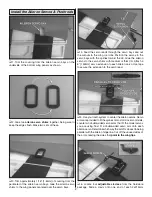
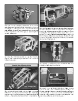
10. Cut four sides from servo arms left over in the hardware bag.
Cut them off close to the center so they are as long as possible.
❏
11. Use a sharp hobby knife to cut a slot in each aileron
9/16" [14.3mm] long and 5/64" [2mm] wide centered in the
triangle block, inline with the aileron ribs as shown. Roughen
the sides of the servo arm pieces with sandpaper and glue
them into the slots using thick CA.
Do not get any glue in
the outer holes of the servo arm pieces!
The outer holes
of the servo arm pieces should protrude beyond the trailing
edge of the ailerons. These will be used to join the top and
bottom ailerons together.
❏
12. Center the ailerons and join the top and bottom together
using adjustable clevises and the remainder of the 2x215mm
aileron pushrods. Tighten the adjustable clevises with 2x4mm
self-tapping screws and cut away the excess pushrod.
FINISH THE MODEL
Install the Landing Gear
❏
1. Measure and mark 1-11/16" [42mm] from the front and
5/32" [4mm] from the bottom of the
wheel pants
. Drill a 1/8"
[3mm] hole at your marks on one side of each wheel pant
(be sure to make a left and right pant). Accuracy during this
step will ensure that your wheels are centered in the pants.
When drilling the hole, make a pilot hole with a smaller bit
fi rst, then enlarge the hole to the correct diameter.


