


❏
#11 blades (5-pack, HCAR0211)
❏
Medium T-pins (100, HCAR5150)
❏
Builder’s Triangle Set (HCAR0480)
❏
36" metal ruler (HCAR0475)
❏
Denatured alcohol (for epoxy clean up)
Here is a list of optional tools mentioned in the manual that
will help you build the Super Sportster EP.
❏
Stick-on segmented lead weights (GPMQ4485)
❏
Top Flite
®
MonoKote
®
sealing iron (TOPR2100)
❏
Top Flite Hot Sock
™
iron cover (TOPR2175)
❏
Top Flite MonoKote heat gun (TOPR2000)
❏
Pro 6-minute epoxy (GPMR6045)
❏
2 oz. [57g] spray CA activator (GPMR6035)
❏
R/C-56 canopy glue (JOZR5007)
❏
CA applicator tips (HCAR3780)
❏
CA debonder (GPMR6039)
❏
Epoxy brushes (6, GPMR8060)
❏
Mixing sticks (50, GPMR8055)
❏
Mixing cups (GPMR8056)
❏
Curved-tip canopy scissors for trimming plastic
parts (HCAR0667)
❏
Robart Super Stand II (ROBP1402)
❏
Masking tape (TOPR8018)
❏
K & S #801 Kevlar thread (for stab alignment)
❏
CG Machine
™
(GPMR2400)
❏
Precision Magnetic Prop Balancer™ (TOPQ5700)
❏
AccuThrow
™
Deflection Gauge (GPMR2405)
• There are two types of screws used in this kit:
Sheet metal screws are pointed
and have a coarse thread.
Machine screws have a squared
off end and a fine thread.
Both screws are designated by a number, the diameter, and
the length. For example a 3 x 8mm screw has a diameter of
3mm and a length of 8mm.
• When you see the term
test fit in the instructions, it means
that you should first position the part on the assembly
without using any glue, then slightly modify or
custom fit
the part as necessary for the best fit.
• Whenever the term
glue is written you should rely upon
your experience to decide what type of glue to use. When a
specific type of adhesive works best for that step, the
instructions will make a recommendation.
• Whenever just
epoxy is specified you may use either
30-minute (or 45-minute) epoxy
or 6-minute epoxy. When
30-minute epoxy is specified it is highly recommended that
you use only 30-minute (or 45-minute) epoxy, because you
will need the working time and/or the additional strength.
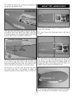
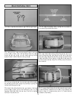
• Photos and sketches are placed before the step they
refer to. Frequently you can study photos in following steps
to get another view of the same parts.
• The stabilizer and wing incidences and motor thrust angles
have been factory-built into this model. However, some
technically-minded modelers may wish to check these
measurements anyway. To view this information visit the web
site at www.greatplanes.com and click on “Technical Data.”
Due to manufacturing tolerances which will have little or no
effect on the way your model will fly, please expect slight
deviations between your model and the published values.
Fuse = Fuselage
Stab = Horizontal Stabilizer
Fin = Vertical Fin
LE = Leading Edge
TE = Trailing Edge
LG = Landing Gear
Ply = Plywood
" = Inches
mm = Millimeters
SHCS = Socket Head Cap Screw
COMMON ABBREVIATIONS
IMPORTANT BUILDING NOTES
Adhesives and Building Supplies
4
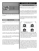
0"
1"
2"
3"
4"
5"
6"
7"
0
10
20
30
40
50
60
70
80
90
100 110 120 130 140 150 160 170 180
Inch Scale
Metric Scale
To convert inches to millimeters, multiply inches by 25.4