GREAT PLANES Super Sportster EP Скачать руководство пользователя страница 19

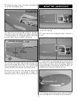
8. To provide an exit for the cooling air, trim the covering

from the six holes in the bottom of the fuselage, behind the
wing saddle.

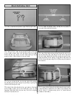
1. Use scissors or a sharp hobby knife to cut the decals from
the sheet.

2. Be certain the model is clean and free from oily fingerprints
and dust. Prepare a dishpan or small bucket with a mixture of
liquid dish soap and warm water-about one teaspoon of soap
per gallon of water. Submerse the decal in the soap and
water and peel off the paper backing. Note: Even though the
decals have a “sticky-back” and are not the water transfer
type, submersing them in soap and water allows accurate
positioning and reduces air bubbles underneath.

3. Position decal on the model where desired. Holding the
decal down, use a paper towel to wipe most of the water away.

4. Use a piece of soft balsa or something similar to
squeegee remaining water from under the decal. Apply the
rest of the decals the same way.

5. When applying the starburst decals to the stabilizer, fin
and wing, let the decal hang off the trailing edge slightly.
Then, use a sharp hobby knife to trim it flush with the trailing
edge. Also, on the wing we cut out each ray of the starburst
and applied them separate. Remember to trim the decal
along the hinge line so that the control surfaces are able to
move, but be careful not to cut the hinges.

Warning: Once the motor battery is connected to the
electronic speed control, stay clear of the propeller.

1. Switch on the transmitter and connect the motor

battery to the electronic speed control. Move the throttle
stick down to the off position. Switch on the speed control
and center the trims. If necessary, remove the servo arms
from the servos and reposition them so they are centered.
Reinstall the screws that hold on the servo arms.

2. With the transmitter and receiver still on, check all the

control surfaces to see if they are centered. If necessary,
adjust the pushrods at the pushrod connectors to center the
control surfaces.

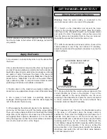
3. Make certain that the control surfaces respond in the

correct direction as shown in the diagram. If any of the
controls respond in the wrong direction, use the servo
reversing in the transmitter to reverse the servos connected
to those controls. Be certain the control surfaces have
remained centered. Adjust if necessary.

4. To operate or “arm” the motor, the throttle stick must be

in the down or off position when the speed control is
switched on. Then, move the throttle stick to full power for 5
seconds, then back down to off. The motor will now run
when the throttle stick is advanced. If it does not, the throttle
reversing switch may be set incorrectly. Disconnect the
motor battery, change the throttle reversing switch and retry
the throttle arming procedure. If the prop is turning the
wrong direction, no air blowing back towards the fuselage,
disconnect and switch the red and black wires between
motor and speed control.

FULL THROTTLE

RUDDER MOVES RIGHT

LEFT AILERON MOVES DOWN

RIGHT AILERON MOVES UP

ELEVATOR MOVES UP

4-CHANNEL

TRANSMITTER

(STANDARD MODE 2)

4-CHANNEL RADIO SETUP

TRANSMITTER

4-CHANNEL

TRANSMITTER

4-CHANNEL

TRANSMITTER

4-CHANNEL

Check the Control Directions

GET THE MODEL READY TO FLY

Apply the Decals

19

Содержание Super Sportster EP

Страница 1: ...turn this kit immediately in new and unused condition to the place of purchase To make a warranty claim send the defective part or item to Hobby Services at the address below Hobby Services 3002 N Apollo Dr Suite 1 Champaign IL 61822 USA Include a letter stating your name return shipping address as much contact information as possible daytime telephone number fax number e mail address a detailed d...

Страница 2: ... manual corrections to the Super Sportster EP ARF visit the Great Planes web site at www greatplanes com Open the Airplanes link then select the Super Sportster EP ARF If there is new technical information or changes to this model a tech notice box will appear in the upper left corner of the page We urge you to join the AMA Academy of Model Aeronautics and a local R C club The AMA is the governing...

Страница 3: ...Using a peak detecting charger reduces the chances of damaging the batteries from over charging We recommend the Great Planes Triton DC Peak Charger GPMM3150 to keep your batteries in good condition 2 The second method of charging your motor batteries is to monitor the voltage of your battery pack with a voltmeter while charging This method is only recommended for NiCd batteries Your charger may h...

Страница 4: ...tom fit the part as necessary for the best fit Whenever the term glue is written you should rely upon your experience to decide what type of glue to use When a specific type of adhesive works best for that step the instructions will make a recommendation Whenever just epoxy is specified you may use either 30 minute or 45 minute epoxy or 6 minute epoxy When 30 minute epoxy is specified it is highly...

Страница 5: ...g Panel 3 Right Wing Panel 4 Stabilizer and Elevator 5 Fin and Rudder 6 Elevator Joiner Wire 7 Tail Gear Assembly 8 Wing Joiners 2 9 Cowl 10 Spinner 11 Prop 12 Electronic Speed Control 13 Main Landing Gear 14 Wheels 2 15 Wheel Pants 2 16 Motor Battery 17 Pushrods 2 Kit Contents Photographed Canopy 1 Control Horn 2 Collet Wire 1 3x10mm Sheet Metal Screw 4 Nylon Landing Gear Strap 2 Plywood Wheel Pa...

Страница 6: ...idents will also be charged sales tax If ordering via fax include a Visa or MasterCard number and expiration date for payment Mail parts orders and payments by personal check to Hobby Services 3002 N Apollo Drive Suite 1 Champaign IL 61822 Be certain to specify the order number exactly as listed in the Replacement Parts List Payment by credit card or personal check only no C O D If additional assi...

Страница 7: ...slots Hint If you have one use a high speed rotary tool to drill the holes 3 Use a sharp 11 blade to cut a strip of covering from all the hinge slots in the wing half and aileron 4 Test fit the ailerons to the wing with the hinges If the hinges don t stay centered stick a pin through the middle of the hinges to hold them in position 5 Clean the aileron torque rod with denatured alcohol to remove a...

Страница 8: ...is acceptable If the wing doesn t fit well or if you can t get close enough to the dihedral specified there may be excess glue inside the wing or irregularities on the joiner Use coarse sandpaper to true the edges and bevel the corners of the joiner and or use a hobby knife to remove any glue from the joiner openings in the ribs on the end of the wing halves 3 Prepare 1 2 oz of 30 minute epoxy Wor...

Страница 9: ...ge and bolt it into position with two 3x30mm machine screws and 3mm washers 1 Using a sharp hobby knife remove the covering from the stabilizer slot at the aft end of the fuselage Also remove the temporary balsa block 2 Mark the center of the trailing edge of the stabilizer Insert the stabilizer into the slot 3 Stick a T pin into the center of the top of the firewall Tie a small loop in one end of...

Страница 10: ...1 hobby knife or the Expert Tip that follows to cut the covering from the stab just inside the lines you marked Use care to cut only the covering and not the wood Cutting the wood will weaken the stab and it may break in flight HOW TO CUT COVERING FROM BALSA Use a 25 watt soldering iron to cut the covering from the stab The tip of the soldering iron doesn t have to be sharp but a fine tip does wor...

Страница 11: ...atured alcohol Masking tape can be used to hold the fin in position until the epoxy cures 13 Trim the covering from the elevator joiner wire slot in the leading edge of both elevator halves 14 Test fit the elevator joiner wire in both of the elevator halves Lay the elevator on a flat surface and check that both halves lay flat and that the leading edge is straight If they are not use pliers to mak...

Страница 12: ... the mark Cut a slot in the leading edge of the rudder to clear the tail gear wire bushing 20 Once satisfied with the fit of the tail gear wire in the rudder apply epoxy in the tail gear wire hole in the leading edge of the rudder Join the rudder to the fin using two CA hinges Before the epoxy cures use thin CA to glue the CA hinges in the rudder and fin following the same procedure used for the a...

Страница 13: ...screws and the nylon mounting plate on the top side of the elevator 4 Connect the pushrod wire to the control horn with a 1 7mm wheel collar and 2 5mm set screw 5 Install the rudder control horn following the same procedure Make sure that the control horn does not interfere with the elevator 1 Install servo arms on the rudder and elevator servos The pushrod mounting holes should be approximately 1...

Страница 14: ... in the receiver Connect the red and black bullet connectors from the ESC to the connectors from the motor Remove the cover from the on off switch Mount the on off switch on the fuselage just behind the servo tray 5 Install the two pushrod connectors on the rudder and elevator servo horns by first inserting the connector through the horn then install a 2mm washer and an 2mm nut on the connector Ap...

Страница 15: ...t the marks and cut the pushrods 3 8 10mm past the bend Attach the pushrods to the aileron servo arm with nylon snap keepers Cut off the excess threads on the aileron torque rods 1 Slide the cowl over the front of the fuselage 2 Slide the prop shaft and collet onto the output shaft of the gear drive The collet has a tapered hole through it The side with the larger hole goes on first 3 Install the ...

Страница 16: ...ews 8 Remove the cowl once more Add a few drops of thin CA to the screw holes in the fuselage to harden the threads Allow the CA to fully harden then mount the cowl 1 Trim the covering from the main landing gear slot in the bottom of the fuselage 2 Insert the two main landing gear wires in the holes in the slot 3 Position two nylon landing gear straps over the landing gear Drill a 1 16 1 6mm hole ...

Страница 17: ...the inside of the wheel pant and glue the wheel pant retainer to the wheel pant with epoxy 8 Install a 3x4mm machine screw in two 3mm wheel collars Remove one of the screws from the landing gear strap and install on the landing gear a wheel collar wheel and a second wheel collar Insert the landing gear in the wheel pant retainer and reinstall the landing gear strap Tighten the 3x4mm machine screws...

Страница 18: ...the fuselage Note that it fits only one way The front is slightly narrower than the aft end 5 To make the battery strap overlap the two pieces of hook and loop material as shown 6 Insert the hook and loop strap through the slot in one side of the battery tray and bring it out the slot in the other side of the tray Adjust it so that the overlap is under the tray Install the battery in the battery c...

Страница 19: ... the electronic speed control Move the throttle stick down to the off position Switch on the speed control and center the trims If necessary remove the servo arms from the servos and reposition them so they are centered Reinstall the screws that hold on the servo arms 2 With the transmitter and receiver still on check all the control surfaces to see if they are centered If necessary adjust the pus...

Страница 20: ...e C G up to 1 4 6mm forward or 1 4 6mm back to change the flying characteristics Moving the C G forward may improve the smoothness and stability but the model may then require more speed for takeoff and make it more difficult to slow for landing Moving the C G aft makes the model more maneuverable but could also cause it to become too difficult to control In any case start at the recommended balan...

Страница 21: ...ore you go flying and at other times as recommended by the radio manufacturer Carefully balance your propeller and spare propellers before you fly An unbalanced prop can be the single most significant cause of vibration that can damage your model Not only will motor mounting screws and bolts loosen possibly with disastrous effect but vibration may also damage your radio receiver and battery We use...

Страница 22: ...oken wires corroded wires on old servo connectors poor solder joints in your battery pack or a defective cell or a damaged receiver crystal from a previous crash Use safety glasses when running the motor Do not run the motor in an area of loose gravel or sand the propeller may throw such material in your face or eyes Keep your face and body as well as all spectators away from the plane of rotation...

Страница 23: ...d spare propellers 13 Tighten the propeller nut and spinner 14 Place your name address AMA number and telephone number on or inside your model 15 If you wish to photograph your model do so before your first flight 16 Range check your radio when you get to the flying field The Super Sportster EP is a great flying model that flies smoothly and predictably The Super Sportster EP does not however poss...

Страница 24: ...otes or having your assistant write them down of what trim or C G changes may be required to fine tune the model so it flies the way you like Mind your battery power but use this first flight to become familiar with your model before landing To initiate a landing approach lower the throttle while on the downwind leg Allow the nose of the model to pitch downward to gradually bleed off altitude Cont...

Отзывы: