background image

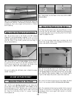
Note: Before reinstalling the cable into the guide, apply a
light coat of oil or petroleum jelly to the cable to prevent
future corrosion.

B. Remove the threaded coupler from the nylon clevis, slide
the cable back into the outer pushrod tube, then solder the
cable to the coupler. Thread the clevis back onto the
coupler. Then attach it to the rudder horn. Make final
adjustments by screwing or unscrewing the nylon clevis at
either end of the cable.

60 Floats Only

After performing steps A and B, continue with step 8.

A. Screw a nylon clevis to the .074" x 12" threaded rod.
Then temporarily fasten the clevis to the rudder horn.
Holding the water rudder on the float and the rudder on the
airplane in a neutral position, determine where the threaded
rod and the cable will be joined with the coupling sleeve.
Then cut the rod to length. Remove the cable from the guide
tube, and then cut the cable to length. Hint: A Great Planes
cut-off wheel (GPMR8200) works well for cutting cable like
this without fraying the end. Cut the guide tube to a length
that will not interfere with the split coupler when it is
soldered onto the cable and the cable moves in and out.

Note: Before reinstalling the cable into the guide, apply a
light coat of oil or petroleum jelly to the cable to prevent
future corrosion.

B. Slide the cable back into the guide tube. Then join the
threaded rod to the cable by soldering the coupling sleeve
to both pieces. Make final adjustments by screwing or
unscrewing the nylon clevis at either end of the cable.

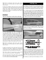
8. Mount another 1/8" plywood mount plate and the

other cut hump strap near the rear of the guide tube.

9. Test the actuation of the water rudder on the floats.

The water rudder and the rudder on the model must both
be neutral and move in the same direction.

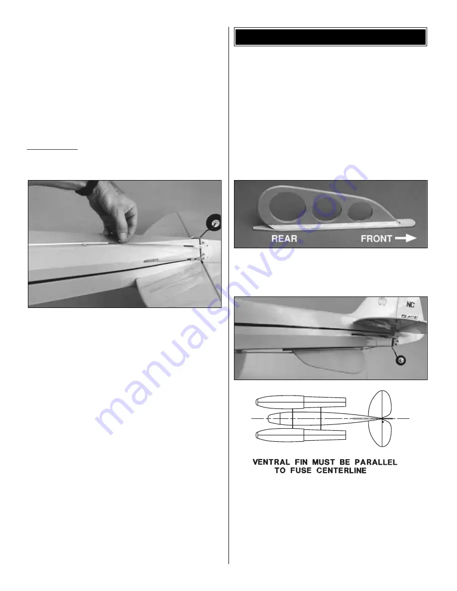
The purpose of the ventral fin is to increase yaw stability.
Some models may be flown successfully without the ventral
fin, but we strongly recommend that you add the ventral fin
to your airplane when flying with Great Planes Sport Floats.

1. Laminate the die-cut 3/32" balsa ventral fins with 

6-minute epoxy. Note: The 60 ventral fin is two pieces of
die-cut 1/8" plywood. Hint: Clamp the ventral fins together
while the epoxy cures by laying weights on top of them over
a flat work surface covered with wax paper. After the glue
has cured, use a sanding block and 150-grit sandpaper to
sand the ventral fin flat, remove any excess glue, and round
the edges. Final sand with 320 to 400-grit sandpaper.

2. Making sure the ventral fin is perpendicular to the 

die-cut 1/8" plywood ventral fin base, glue the pieces
together with medium CA. Then glue the 1/4" balsa triangle
stock to the fin and base.

3. Cover the assembled ventral fin to match your model.

Then mount it to the bottom of the fuselage right on the
centerline of the fuselage. The suggested mounting method
is double-sided foam mounting tape. An alternate mounting
method would be to use #2 x 3/8" sheet metal screws. If you
use screws, 1/8" plywood blocks should be glued to the
inside of the bottom sheeting where the screws are located.

4. Balance your airplane again, after adding the ventral fin.

VENTRAL FIN

19

Содержание Sport Floats

Страница 1: ...be assumed nor accepted for any damage resulting from the use by the user of the final user assembled product By the act of using the user assembled product the user accepts all resulting liability I...

Страница 2: ...andling characteristics on the water and ultra smooth realistic takeoffs Of course the Great Planes Sport Floats will work well with other models too The 20 40 or 60 Sport Floats may be properly assem...

Страница 3: ...M is the Great Planes brand HCA is the Hobbico brand TOP is Top Flite IMPORTANT For your model to handle properly on the water and in the air the Sport Floats must be built on a flat surface Also a re...

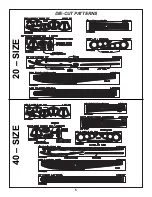
Страница 4: ...4 DIE CUT PATTERNS 60 SIZE...

Страница 5: ...5 DIE CUT PATTERNS 20 SIZE 40 SIZE...

Страница 6: ...re it fully cures 1 Trial fit the die cut 3 32 balsa upper float side lower float side and aft float side Make adjustments if necessary When satisfied with the fit use thin CA to glue the three pieces...

Страница 7: ...eck from former C forward 5 Lay waxed paper over your flat building board and position all the formers except A and I on the deck Make sure the notches in the formers fit all the way down to the deck...

Страница 8: ...ng photo 3 Cut a 3 16 x 3 16 forward stringer to fit in the notches of formers E to A do not attempt to bend the stringer down to the notches in former A at this time Use a pen to make marks every 1 2...

Страница 9: ...the center and should be placed so it covers half of the keel Make adjustments if necessary and bevel the edges of the aft bottom sheets that contact each other in the center Note An embossed arrow i...

Страница 10: ...d arrows to aid in final alignment 4 Referring to the sketch rough sand the entire float with a sanding block and 150 grit sandpaper blending the sides to the deck and the bottoms to the side Sand all...

Страница 11: ...rototype 60 floats mounted on our Great Planes J 3 Cub 60 are covered with MonoKote film and were really put to the test Following are instructions for both covering methods 1 Seal all seams except ar...

Страница 12: ...ing you may do the top and sides first then the bottom If you work quickly you can save the paint brush by cleaning it with alcohol before the resin begins to thicken 7 Carefully sand the entire float...

Страница 13: ...this yields a slight positive wing incidence in relation to the floats and the airplane will tend to rise off the water at the correct time If you have a model with a symmetrical wing the wing incide...

Страница 14: ...solder 1 Match the shorter front strut with the front cross brace and the taller rear strut with the rear cross brace The matching struts and cross braces are the ones that fit together the best Note...

Страница 15: ...hem with a 12 or 13 64 drill bit Mount the bearings to the floats with 4 40 x 1 2 screws 2 Temporarily join the floats to the struts by inserting them into the bearing mounts Use a felt tip pen to mar...

Страница 16: ...per bearing mount placement 2 Temporarily join the floats to the struts with the 5 32 wheel collars The following instructions show the Great Planes J 3 Cub 20 and 40 Use the instructions sketches and...

Страница 17: ...n the nylon swivel 1 8 past the end 4 Loosely install the rudder on the right float with two flat straps two 1 8 hump straps and four 2 x 3 8 sheet metal screws Adjust the bottom of the rudder bracket...

Страница 18: ...de tube to the aft strut with a nylon tie 8 Drill a 1 16 hole and secure the cable guide tube to the mount plate with one of the cut off hump straps and 2 x 3 8 sheet metal screws 20 40 Floats only Af...

Страница 19: ...rewing the nylon clevis at either end of the cable 8 Mount another 1 8 plywood mount plate and the other cut hump strap near the rear of the guide tube 9 Test the actuation of the water rudder on the...

Страница 20: ...g around in the water to learn the handling characteristics and see if you have built in enough throw on the water rudder Make adjustments if required During taxiing hold up elevator to keep the nose...

Страница 21: ......

Отзывы: