❏
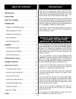
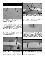
4. Assemble the Nylon rudder bearing, rudder post,
aluminum bracket and nylon control horn as shown in
the photo. Hold the control horn in place with a #2 x 3/16"
[4.8mm] screw.
❏
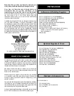
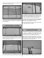
5. Assemble the water rudder to the aluminum bracket with a
4-40 x 1/4" [6.4mm] socket head cap screw and 4-40 lock
nut. Tighten the nut, but leave it loose enough that the water
rudder can pivot freely in the bracket. If the bracket does not
have a hole drilled in it, use a 1/8" drill to drill the hole.
❏
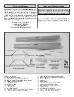
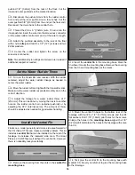
6. Drill a 5/64" [2mm] hole in the aluminum bracket and
rudder post at the location shown in the above photo,
making sure the water rudder and control horn are aligned
as shown. Install a 2-56 x 3/8" [9.5mm] screw and 2-56 nut
to hold the bracket to the rudder post. Use Great Planes Pro
Threadlocker
™
to hold the nut in place.
Hint: Center punch the bracket before drilling the hole.
❏
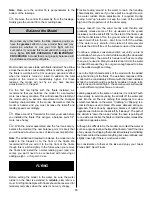
7. Install a screw-lock connector, nylon retainer and
4-40 x 1/8 [3.2mm] socket head cap screw in the outer
hole of the long tiller arm on the water rudder. Also install
the rubber band.
If you are installing a servo inside the right float, proceed to
step 2.
❏
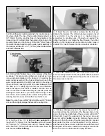
1. Do this step only if you are installing a pushrod from the
aircraft rudder to the water rudder. Mount the water rudder
assembly in the location shown in the above photo. The top of
the mounting bracket should be even with the top of the float,
on the centerline of the transom (rear of the float). Mark the
location of the holes in the mounting bracket on the transom.
Drill a 5/64" [2mm] hole at the marked locations and mount the
water rudder assembly to the transom with two #4 x 1/2"
[12.7mm] sheet metal screws and two #4 flat washers.
Proceed to “Prepare the Model” on Page 10.
Install the Water Rudder
7


