background image

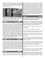
1. Use 5-minute epoxy to glue the three plywood 

forward

wing joiners 

together and the two 

aft wing joiners

together. Use clothespins or c-clamps to clamp the joiners
together until the epoxy cures. Wipe off any excess epoxy
with a paper towel and isopropyl alcohol before it cures.
Draw a vertical 

centerline

on the forward and aft wing joiners. 

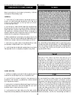
2. Use a sharp hobby knife to cut the covering from the

servo cord exits

on the top of each wing half. Carefully

untie the string from the stick at the root rib and route the
string through the servo cord exit. Re-tie the strings around
the stick.

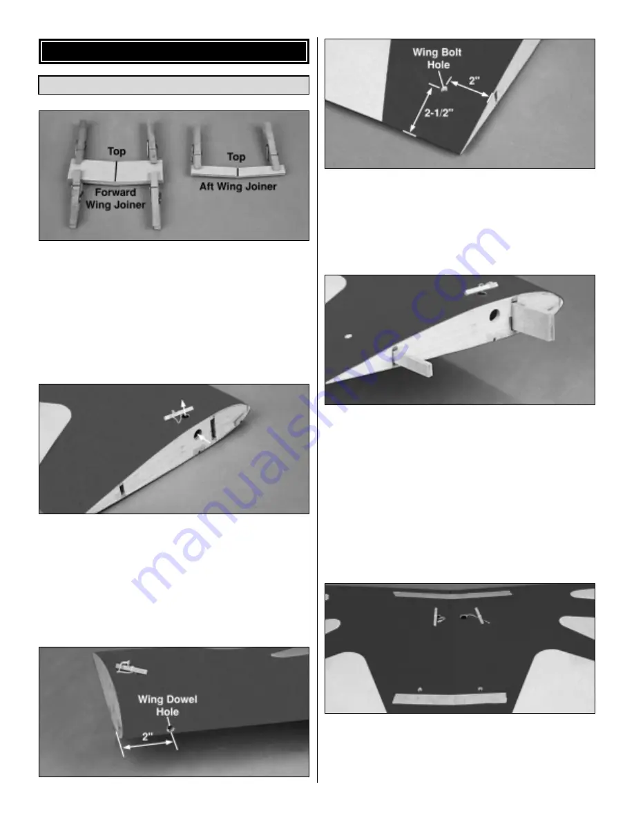
3. Use a sharp hobby knife to cut the covering from the

wing dowel holes

in the leading edge and the 

wing bolt

holes

at the trailing edge of each wing half. The wing dowel

holes are approximately 

2" [50.8mm]

from the wing root.

The wing bolt holes are approximately 

2" [50.8mm]

from

the wing root and 

2-1/2" [63.5mm]

from the trailing edge.

4. Test fit the wing joiners in both wing halves. A snug fit

is desirable. If the joiners do not fit properly, lightly sand the
edges and sides of the joiners. 

Note:

The plywood wing

joiners have a slight dihedral angle. This angle should point
toward the top of the wing. When satisfied with the fit of the
wing joiners, use 

30-minute epoxy

to glue the joiners in the

left wing half. Use plenty of epoxy, making sure the joiners
are glued to the spars and shear webs. Before the epoxy
cures, make sure the joiners are straight and in good
contact with the spars. Wipe off any excess epoxy from the
root rib and the wing covering using a paper towel
dampened with isopropyl alcohol.

5. Test fit the two wing halves together. The wing halves

should seat together without any gaps and the front and
back edges of each wing should line up with each other.
Completely cover the exposed portion of the wing joiners,
spars and root ribs with 30-minute epoxy. Slide the two

Join the Two Wing Halves

WING ASSEMBLY

6

Содержание spacewalker

Страница 1: ...bled product By the act of using the user assembled product the user accepts all resulting liability If the buyer is not prepared to accept the liability associated with the use of this product the bu...

Страница 2: ...which has more than 2 500 chartered clubs across the country Through any one of them instructor training programs and insured newcomer training are available Contact the AMA at the address or toll fr...

Страница 3: ...igure 1 4 Foam Rubber HCAQ1000 Switch and Charge Jack GPMM1000 Large Scale Control Horns 2 24 Servo Extension 2 Y Harness These are the building tools that are required We recommend Great Planes Pro C...

Страница 4: ...you intend to fly the SpaceWalker ARF at IMAA events it may be necessary to replace the 2 56 pushrods clevises and control horns with 4 40 pushrods clevises and control horns designed for 1 4 scale ai...

Страница 5: ...eeper 4 CA Hinge Strip 1 14 oz Fuel Tank 1 Screw Lock Pushrod Connector 1 Pushrod Connector Retainer 1 Description Qty 4 40 Hex Nut 6 4 40 Lock Nut 4 8 32 Blind Nut 4 2 56 x 1 8 Set Screw 1 2 56 x 5 8...

Страница 6: ...8mm from the wing root and 2 1 2 63 5mm from the trailing edge 4 Test fit the wing joiners in both wing halves A snug fit is desirable If the joiners do not fit properly lightly sand the edges and sid...

Страница 7: ...ith the wing centered on the fuselage center the plywood wing bolt plate on the aft edge of the wing Trace the outline of the wing bolt plate onto the wing 4 Use a sharp hobby knife to trim the coveri...

Страница 8: ...nd ease of installation We trust even our best show models to these hinges but it is essential to install them correctly Please read the following instructions and follow them carefully to obtain the...

Страница 9: ...of the vertical fin and the rudder balance tab Mark the tailgear arm location where it will enter the leading edge of the rudder 8 Drill a 3 32 2 4mm hole 1 1 4 31 7mm deep in the leading edge of the...

Страница 10: ...ach the wheel pant bracket to the inside of the wheel pant with two 4 x 1 2 sheet metal screws and 4 washers 6 Drill a 3 16 4 7mm hole in the bottom of the pant aligned with the 3mm hole in the side o...

Страница 11: ...t the spreader bar from the supplied Great Planes adjustable engine mount Use a hobby knife to remove any flashing left over from the molding process so that the halves fit together without any bindin...

Страница 12: ...bration Plug the servos receiver switch and Y harness into the receiver Secure the receiver in the fuselage with a couple of scrap sticks glued to the sides of the fuselage Note Do not permanently mou...

Страница 13: ...dowel 11 Cut the 8 203mm shrink tubing into four 2 50 8mm pieces Slide a 2 50 8mm piece over each end of the wood dowel and pushrod Use a heat gun to shrink the tubing tight around the dowel Apply sev...

Страница 14: ...xit slots Hint Bend the pushrods apart slightly It s best to guide one pushrod out one of the pushrod exits Align the second rod with the other pushrod exit and use a hobby knife or small flat screwdr...

Страница 15: ...d over the clevis Make a 90 bend in the pushrod at the mark you made in step 7 Insert the aileron pushrod in the aileron servo horn and secure it with a nylon Faslink Cut the excess pushrod so it slig...

Страница 16: ...nk must face the top of the fuselage Route the fuel tubing through the firewall Use a stick not included to secure the fuel tank in the fuselage Optional A third piece of fuel tubing may be installed...

Страница 17: ...pushrods at the servo horns to control the amount of throw You may also use the ATV s if your transmitter has them but the mechanical linkages should still be set so the ATV s are near 100 for the be...

Страница 18: ...sition of the receiver battery If nose weight is required first place the receiver battery under the fuel tank This may be all that is required to balance the plane If you are unable to obtain good ba...

Страница 19: ...still have control While you work the controls have a helper stand by your model and tell you what the control surfaces are doing Repeat this test with the engine running at various speeds with a hel...

Страница 20: ...ual rates on your transmitter especially if you are taking off into a crosswind For all models it is good practice to gain as much speed as the length of the runway will permit before lifting off This...

Страница 21: ...xt move and plan each maneuver before you do it Impulsively jamming the sticks without any thought is what gets most fliers in trouble rather than lack of flying skill Happy Landings Engine Mount Temp...

Страница 22: ...t carburetor in back It s generous with power but economical on fuel consumption and comes with both muffler and glow plug to increase your value Also included warranty protection for 5 years Great Pl...

Страница 23: ...nce using the PowerCore MKII Power Pack HCAP0901 It contains a rechargeable 12V 1 2Ah lead acid battery and mounts for securely attaching to the TorqMaster starter GPMR8500 Bench Topper The Great Plan...

Страница 24: ...24 BUILDING NOTES Kit Purchased Date Where Purchased Date Construction Started Date Construction Finished Finished Weight Date Of First Flight FLIGHT LOG...

Отзывы: