a nylon
Faslink.
Cut the excess pushrod so it slightly
protrudes out of the Faslink.
Note:
If necessary, enlarge the hole in the servo arm with a
5/64" [2mm] drill bit (or a #48 bit for precision).
❏
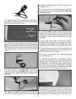
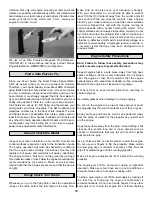
18. In the second wooden dowel, drill 5/64" [2mm] holes
through the dowel, 2" [50.8mm] from each end. On one of
the ends, also drill a hole 1-1/2" [38mm] from the end. On
each end of the dowel, use a hobby knife to cut a groove
from the holes to the end of the dowel, deep enough for a
2-56 threaded pushrod to fit in. The groove for the 1-1/2"
[38mm] hole should be on the opposite side from the
groove for the 2" [50.8mm] hole.
❏
19. Cut 1-1/2" [38mm] off of the non-threaded end of a
2-56 x 12" threaded pushrod. From the threaded end of a
2-56 x 36" pushrod, cut an 11" [279.4mm] long piece. Cut a
second non-threaded 11" [279.4mm] piece from the same
36" pushrod. Make a 90° bend 1/4" [6.4mm] from the non-
threaded end of the 10-1/2" and both 11" pushrods. Insert
the two 11" [279.4mm] pushrods in the holes, 2" [50.8mm]
from the end of the wooden dowel. The 10-1/2" [266.7mm]
pushrod is inserted in the hole 1-1/2" [38mm] from the end.
❏
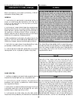
20. Slide a 2" [50.8mm] piece of shrink tubing over each
end of the wood dowel and pushrods. Use a heat gun to
shrink the tubing tight around the dowel and use thin CA to
secure it to the dowel. This is now the elevator pushrod.
❏
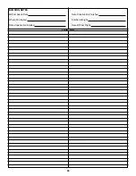
21. Following the same procedure used to install the
rudder pushrod, insert the elevator pushrod into the
fuselage with the two threaded rods exiting out the elevator
exit slots.
Hint:
Bend the pushrods apart slightly. It’s best to
guide one pushrod out one of the pushrod exits. Align the
second rod with the other pushrod exit and use a hobby
knife or small flat screwdriver to guide it out the exit. Slide
silicone clevis retainers over the threaded rods and screw
nylon clevises 14 turns onto the threaded rods.
❏
22. Attach a control horn to both clevises. Align the
adjustment holes in the control horns with the hinge line of
the elevator. Mark the control horn’s mounting holes.
❏
23. Drill a 3/32" [2.4mm] hole at each mark. Mount the
elevator control horns to the elevators with the backing
plate and 2-56 x 5/8" machine screws. Slide the silicone
retainer over the clevis to secure it in place.
❏
24. With the elevator servo centered and the elevators in
the neutral position, use a felt-tip pen to mark where the
pushrod crosses the mounting holes in the servo arm.
❏
25. Make a 90° bend at the mark you made. Insert the
elevator pushrod in the elevator servo horn and secure it
with a nylon Faslink. Cut the excess pushrod so it slightly
protrudes out of the Faslink.
Note:
If necessary, enlarge the
hole in the servo arm with a 5/64" [2mm] drill bit (or a #48
drill for precision).
❏ ❏
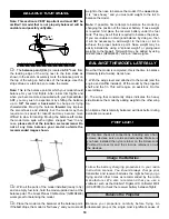
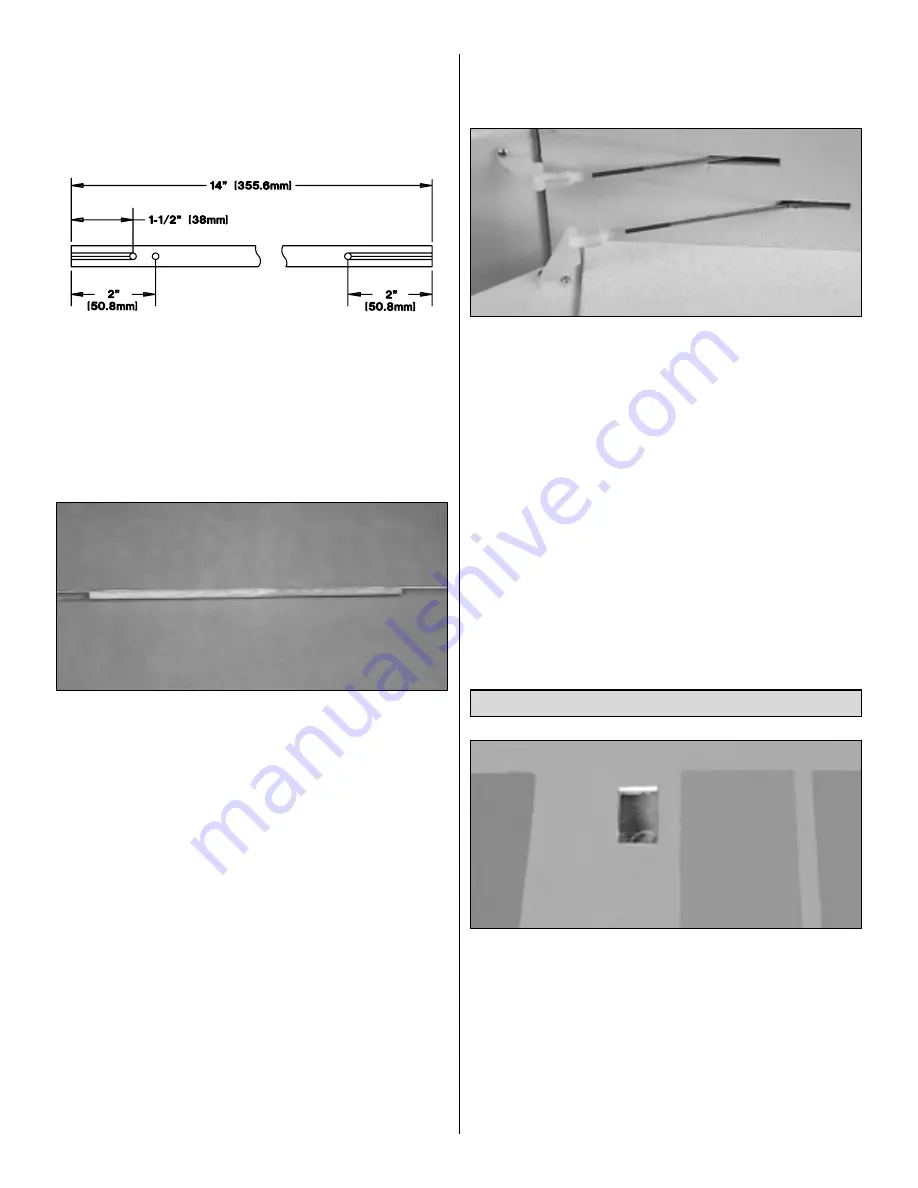
1. Trim the covering from the aileron servo tray on the
bottom of the right wing half.
❏ ❏
2. Plug a 24" [609.6mm] servo extension into the
aileron servo. As a precaution, use tape or shrink tubing
(not included) to prevent the connectors from separating.
❏ ❏
3. Carefully pull the string in the aileron servo bay out
enough to tie it to the end of the 24" servo extension.
Gently
pull the extension through the wing until it exits at
the center of the wing.
Install the Aileron Servos
14


