❏ ❏
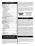
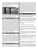
4. Mark the aileron servo mounting hole locations on
the wing. Remove the aileron servo and drill a 1/16"
[1.6mm] hole at each mark. Mount the aileron servo in the
wing with the mounting screws included with the servo.
❏ ❏
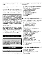
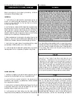
5. Trim three of the four arms from a cross servo arm.
Plug the aileron servo into your receiver, switch the radio
system on and center the aileron servo. Install the servo
arm on the servo so that it is perpendicular to the centerline
of the servo. Screw a nylon clevis 14 turns onto a 2-56 x
12" threaded pushrod. Attach the clevis to a control horn
and position the control horn on the aileron so that the
pushrod is aligned with the servo arm, and the adjustment
holes in the horn are aligned with the aileron hinge line.
Mark the horn mounting holes.
❏ ❏
6. Mount a large scale control horn (not included), to
the aileron following the manufacturer’s instructions.
❏ ❏
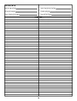
7. With the ailerons in the neutral position, use a felt-tip
pen to mark where the pushrod crosses the mounting holes
in the servo arm.
❏ ❏
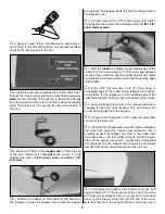
8. Slide a silicone retainer on the pushrod and over
the clevis. Make a 90° bend in the pushrod at the mark you
made in step 7. Insert the aileron pushrod in the aileron
servo horn and secure it with a nylon Faslink. Cut the
excess pushrod so it slightly protrudes out of the Faslink.
Note:
If necessary, enlarge the hole in the servo arm with a
5/64" [2mm] drill bit (or a #48 drill for precision).
❏
9. Return to step 1 of “Install The Aileron Servos” and
install the second aileron servo.
Note:
Install the servo
arms so that they both point outward, toward the wing tips.
❏
10. Plug both ailerons into the “Y” cable.
❏
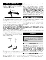
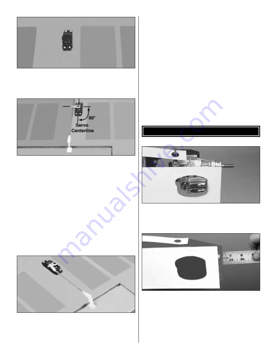
1. Use strips of thin cardboard or plastic to make
templates to locate the head of the engine and needle
valve. Tape the templates to the fuselage, accurately
indicating the position of the engine head and needle valve.
❏
2. Place the backplate of your spinner on the engine and
check that the distance between the firewall and the
backplate is 6-1/4" [158.7mm]. Remove the engine from the
engine mount, leaving the templates in place. Position the
cowl on the fuselage so the forward edge is 3/32" [2.4mm]
aft of the measurement you just made, or 6-5/32"
[156.3mm] in front of the firewall. Align the cowl on the
fuselage and lightly mark the location of the rear of the cowl
on the fuselage top.
INSTALL THE COWL
15


