GREAT PLANES SlowPoke Скачать руководство пользователя страница 22

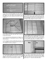
2. Determine the location of the pushrod exit holes from

the plan. Use a hobby knife to sharpen one end of a piece
of 3/16" (outer diameter) brass tubing, then use this tubing
to cut the pushrod exit holes (you may use a 3/16" drill bit,
but the brass tube makes a much neater cut). Hint: You
may chuck the brass tube into your drill to aid in cutting
these holes.

3. From the 36" long gray outer pushrod tube, cut two 13-

1/2" long pieces. Insert the 13-1/2" tubes through the holes
you just cut in the fuse side and through formers F5 and
F4B so that 1/4" extends past F4B and out the fuse sides. 

4. Glue the tubes to the fuse sides, F5 and F4B with 

thin CA.

5. Cut off the tubes at the exit points and sand them flush

with the fuse sides.

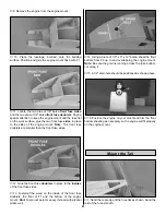
6. Mount the wing on the fuse. Trim the wing bolts off 1/8"

above the WBP.

7. Turn the plane right side up. Glue the die-cut 3/32

balsa former F6 vertically in its slots.

8. Accurately measure the trailing edge of the stabilizer

and mark the center point.

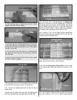
9. Lay the stab in position (the TE should be flush with the

TE of the fuse) with the center point lined up with the center
of the fuse. Carefully check the stab alignment by standing
directly behind the fuselage and “eyeballing” whether or not
the stab is parallel to the wing. Sand the stab saddle (a little
at a time!
) until the stab aligns properly with the wing. Also,
using your string, measure from the stab tips to a center point
on the front of the fuse to make sure the stab is aligned.

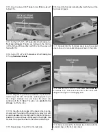
10. Using 6-minute epoxy, glue the stab to the fuse. Hold

or pin it in proper alignment until the epoxy has fully cured.
Note:  Wipe off any excess epoxy, with a cloth moistened
with alcohol, before it sets.

11. Carefully align the fin on the stab. The fin must be

positioned perpendicular to the stab and must line up
with the fuselage centerline EXACTLY! 
Sand the slot in
F6, if necessary to properly align the fin. Glue the fin in
place.  Note: The turtle deck stringers and the turtle deck
top will also lock the fin into position.

12. Remove the wing from the fuse.

22

Содержание SlowPoke

Страница 1: ...mbly no liability shall be assumed nor accepted for any damage resulting from the use by the user of the final user assembled product By the act of using the user assembled product the user accepts al...

Страница 2: ...her a sophisticated working model that functions very much like an actual airplane Because of its realistic performance the SlowPoke if not assembled and operated correctly could possibly cause injury...

Страница 3: ...the Top Flite brand and HCA is the Hobbico brand 4 Channel Radio with 3 Servos Engine See Engine Selection Spare Glow Plugs O S 8 for most 2 stroke engines OSMG2691 O S Type F for most 4 stroke engin...

Страница 4: ...epoxy is specified you may use either 30 minute epoxy or 6 minute epoxy When 30 minute epoxy is specified it is highly recommended that you use only 30 minute epoxy because you will need the working t...

Страница 5: ...around the parts with a hobby knife After punching out the die cut parts use your bar sander or sanding block to lightly sand the edges to remove any die cutting irregularities or slivers 3 As you id...

Страница 6: ...6 DIE CUT PATTERNS...

Страница 7: ...d glue the stab bracing in place 7 Remove the pins and sand the top and bottom of the stab smooth Note Be careful not to sand any dips in the stab bracing 8 Sand the leading edge and the tips to a rou...

Страница 8: ...glue the fin trailing edge fin base and the fin leading edge Note The fin trailing edge stops at the top of the stab It does not go to the bottom of the fuse 3 From a 3 16 x 3 16 x 24 balsa stick fit...

Страница 9: ...of the elevator and rudder to a V as shown on the plan 2 Sand both sides of the elevator assembly smooth 3 Use a bar sander and 150 grit sandpaper to round the tail surfaces as shown on the plan Note...

Страница 10: ...om the front so that they will not interfere with the top spar or the shear webs 6 Cut six 1 8 x 3 16 x 24 balsa sticks to 21 3 16 long making the auxiliary spars 7 Postion three auxiliary spars over...

Страница 11: ...which extends outboard past ribs W3 Note Be sure to align it with the wing plan not the aft end of the ribs 18 From a 1 16 x 3 x 24 sheet cut a 10 7 16 long LE sheet Position the LE sheet aligning th...

Страница 12: ...e top TE sheet previously applied Glue it to the ribs the auxiliary spar and the filler block 25 Select the two 4 7 8 long basswood landing gear rails Glue them into the W2 ribs with epoxy 26 Glue the...

Страница 13: ...ough each rail being careful not to drill through the top of the wing 1 Cover the right outer wing panel plan with Plan Protector Pin the die cut 1 16 balsa TE sheeting in position 2 From a 1 16 x 3 x...

Страница 14: ...ly DG gauge to set the angle of T1 and glue T1 in place Use a square to be sure T2 is vertical and glue it in place 13 Position the 1 16 die cut balsa T3 rib on the plan aligned with the inboard edge...

Страница 15: ...bottom TE sheet Glue it in place 22 From the leftover 1 16 x 3 balsa sheet cut three 4 1 8 long sheets and edge glue them in position as you did with the bottom sheeting Hint Remember to trim the thir...

Страница 16: ...uter wing panel to the wing center section When satisfied with the fit glue the outer panel to the center section with epoxy and glue the wing joiners to ribs T1 and T2 Note Do not disturb the wing un...

Страница 17: ...he building board 5 From a 3 16 x 3 16 x 30 balsa stick fit and glue the bottom aft fuse stringer and the aft fuse brace in place 6 Glue the die cut 1 8 balsa pushrod exit plate in place 7 From a 1 8...

Страница 18: ...a formers F3 and F5 as you go Note The embossed labels on F3 and F5 face the front of the plane and are upside down on the work surface at this time 18 Confirm that the fuse sides are perpendicular to...

Страница 19: ...ng over to the other tip and see if it aligns with the same point If it does not shift the wing and mark the new location of the tip by adjusting the position of the tape on the string Do this until t...

Страница 20: ...t your engine 5 Position the engine on the mount so there is a 1 16 gap between the rear of the engine and the slot in the mount 6 Mark the engine mount holes with a pencil lead or a T pin Remove the...

Страница 21: ...oublers in place to the insides of the front fuse sides 13 Fuelproof the wood on the inside of the front fuse doublers the front of F1 and the bottom of the engine mount Hint Fuel proof paint or epoxy...

Страница 22: ...the trailing edge of the stabilizer and mark the center point 9 Lay the stab in position the TE should be flush with the TE of the fuse with the center point lined up with the center of the fuse Care...

Страница 23: ...t comes to a point at the TE of the fin Glue to F6 and the fin Repeat this step for the other five turtle deck stringers 5 Using the full size template on the plan make the turtle deck top from a 1 4...

Страница 24: ...e fuse top 14 Glue the bottom edge of the sheet to the fuse top Liberally wet the outside of the sheeting by spraying it with an ammonia water mix Gently bend the sheet until you can position it in a...

Страница 25: ...e servo arm 5 Solder the threaded coupler to the 24 long throttle cable with silver solder Screw a nylon clevis onto the coupler 6 Mount the engine Slide the throttle cable through the guide tube you...

Страница 26: ...e trailing edge of the fuse at the marks you made for the nylon tail gear bearing Without using any glue test fit the rudder to the fin with the tail gear wire When satisfied with the fit remove and s...

Страница 27: ...with the elevators and stab Cut the covering from the hinge slots don t just slit the covering but remove a small strip the size of the hinge slot 2 Drill a 3 32 hole 1 2 deep in the center of each hi...

Страница 28: ...the next step in balancing your model A model which is not laterally balanced properly may exhibit a variety of unpleasant tendencies such as uncharacteristic tip stalls This aircraft when balanced p...

Страница 29: ...rewall Tail weight may be added by using Great Planes GPMQ4485 stick on lead weights 4 Permanently mount your receiver and battery If possible first attempt to balance the model by changing the positi...

Страница 30: ...ced pilot when learning to operate engines Use safety glasses when starting or running engines Do not run the engine in an area of loose gravel or sand the propeller may throw such material in your fa...

Страница 31: ...is one thing in mind pull back on the throttle stick to slow the model down This will make everything happen a little slower and allow yourself time to think and react Add and practice one maneuver at...

Страница 32: ...TWO VIEW...

Отзывы: