


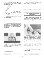


D 5. Snap the nylon clevis onto the control horn (the
second hole from the outside) and lay the pushrod across
the servo horn.
D 6. Mark where the pushrod wires cross the holes in
the servo horn. Remove the pushrods and make a Z-bend
in the rods at that point.
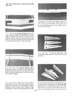
servo rails (FUN1F19). If you have a servo tray for 3
servos that will fit you can use it on top of the servo rails.
NOTE: when mounting these servos make sure they are as
close to the fuselage bottom as possible. The servo rails
are cut to fit on the ledge formed by the fuselage doubler
but they can be cut to fit between the doublers so the servos
can be installed lower in the fuselage.
D 9. Tack glue the nylon control horns (NYLON03)
on the elevator and rudder in the positions shown on the
plan and mark the mounting hole locations. Drill 3/32"
holes at these locations. Remove the horns.
D 7. Work the Z-bends into the servo horns (use a hole
approximately 1/2" from the center of the horn) and snap
the clevis back onto the control horn. Check the operation
of the ailerons. (See page 33 for the recommended amount
of aileron movement and page 36 for the correct direction
of movement).
IMPORTANT!
D 10. Harden the balsa in the area of the control
horns (on both sides of all control surfaces) by
poking several holes with a pin, then applying thin
CA glue. Sand smooth.
D 11. Mount the horns with 2-56 screws (SCRW002)
and the nylon nutplates which were attached to the horns.
2-56 x 5/8"
Machine Screw
Nylon Nut Plate
D 12. Screw a nylon clevis (NYLON 17) onto the threaded
end of each long steel wire pushrod (WIRES 17). NOTE:
Screw them on all the way until the threads are pro-
truding inside the clevis.
ELEVATOR, RUDDER AND
THROTTLE SERVOS
REMEMBER: Plan your servo installation carefully, as
your setup may differ from the plans and photos, depend-
ing on which engine you use.
D 13. Cut the short length of 1/8" diameter plastic
tube (PLTB014) into several pieces, approximately 1/4"
long. Slide at least six of these pieces onto each of the long
pushrod wires and space them approximately 2-1/2" apart
(do not glue yet). NOTE: If these lubes do not slide on
easily, cut them to a shorter length.
SPACER
D 8. Mount the elevator, rudder and throttle servos in
the fuselage using the 1/4" x 3/8" x 2-3/4" basswood
NOTE: While installing the pushrods, position the above
plastic tube spacers so they always slay inside the pushrod
32
Содержание FUN-ONE
Страница 5: ...5...


