bolts will fit back in, then reinstall the wing. Sand the
fairing to blend in with the fuselage and the wing. Add
filler where necessary to make a nice smooth fairing.
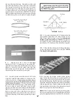
Note: If you want to only have small holes to insert a
screwdriver through and keep the bolts captive, make
marks on the wing and hatch showing the center of each
bolt. Then, after gluing the tops into place, drill a hole
from the top of the wing just large enough to get your
screwdriver through. When doing this the threaded por-
tion on the bolts can be no longer than 5/8". If you ever
break a wing bolt (which is not probable) it will be
necessary to enlarge these holes to replace the bolt, but it
looks nicer with small holes.
SHAPING AND SANDING
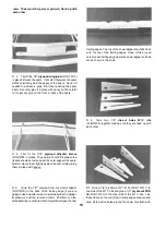
D 1. Using a sanding block and 80-grit sandpaper,
sand the fuselage comers to a rounded shape. Refer to the
cross-sections on the fuse plan, and try to sand the corners
to the same shape as shown on the plan.
D 2. Vacuum the entire structure thoroughly, then
inspect for any poorly glued joints and gaps. Apply
additional glue and/or balsa filler as necessary, then sand
the entire fuselage and wing smooth.
D 5. Attach the clevises to the clevis connectors, then,
with the ailerons in the neutral position, mark the pushrod
wires where they cross the holes in the servo arm. Remove
the pushrods and make a "Z-bend" in the rods at that
point, using a "Z-bend pliers" or a standard pliers.
D 6. Remove the servo wheel from the servo and work
the Z-bends into the wheel (NOTE: You may have to
enlarge the servo wheel holes with a 5/64" diameter drill
bit). Replace the servo wheel and check the operation of
the ailerons. (See page 33 for the recommended amount
of aileron movement).
INSTALL PUSHRODS AND RADIO
COMPONENTS
(ONE AILERON SERVO):
D 1. Mount the servo in the wing using the screws
provided with the radio.
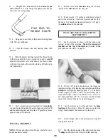
D 2. Screw the nylon aileron clevises (NYLON21)
approximately 2/3 of the way onto the threaded end of the
two 12" steel wire pushrods (WIRES 16).
Nylon Aileron Clevis
D 3. Screw the nylon aileron clevis connectors onto
the aileron torque rods.
N y l o n Clevis Connector
D 4. Cut two arms off of a 4-arm servo horn and install
the horn on the servo. The horn should be parallel to the
wing TE.
(TWO AILERON SERVOS):
D 1. Mount the servos in the wing using the screws
provided with the radio.
D 2. Cut three arms off of a 4-arm servo horn and
install a horn on each servo. The horns should be parallel
to the wing TE and pointing towards the tips of the wing.
D 3. Screw a nylon clevis (NYLON 17) onto each 12"
threaded steel pushrod (WIRES 16). NOTE: Screw
them on all the way until the threads are protruding
inside the clevis.
Nylon Clevis
D 4. Tack glue a nylon control horn (NYLON03)
onto each aileron, directly behind the outer side of each
servo. The front of the control horn should be just behind
the bevel on the aileron. Mark where the mounting holes
should be and drill a 3/32" hole for each screw.
31
Содержание FUN-ONE
Страница 5: ...5...


