background image

11

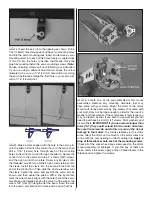
Install the Elevator and Rudder

Servos and Pushrods

 1. For both the rudder and elevator servo install a servo 

extension onto the servo lead. With the Futaba 3103 servo a 
6" [152mm] extension is adequate. Other brands may require 
a longer or shorter extension. To reach the receiver you need 
9" [230mm] of wire from the servo to the receiver. Secure the 
servo lead to the extension with tape, a piece of shrink tube or 
some other method to keep them from coming unplugged.


RETAINER

 2. Remove three of the four arms from the servo horn, 

leaving the longest arm in place. Enlarge the last hole in 
the servo arm with a #57 drill. Install an aluminum screw 
lock connector into the hole and lock it in place with a nylon 
retainer. Install a set screw into the screw lock connector. 
Install the servo into the opening on the right side of the 
fuselage using the hardware that came with the servo. Center 
the servo and install the servo arm as shown.

 3 Install one of the .95 x 360mm [14"] long pushrod wires 

into the left side of the fuselage, sliding it into the servo 
compartment. Slide the wire into the hole in the screw lock 
connector and lightly tighten the set screw against the wire.

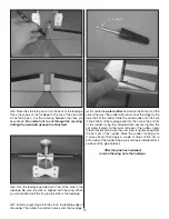
 4. Install a screw lock connector into the outer hole of 

a control horn. Slide the screw lock connector onto the 
pushrod wire. Position the control horn as shown, mark the 

Содержание ElectriFly PBY Catalina

Страница 1: ...to the place of purchase To make a warranty claim send the defective part or item to Hobby Services at the address below Hobby Services 3002 N Apollo Dr Suite 1 Champaign IL 61822 USA Include a lette...

Страница 2: ...del of this famous twin engine airplane For the latest technical updates or manual corrections to the ElectriFly PBY Catalina visit the Great Planes web site at www greatplanes com Open the Airplanes...

Страница 3: ...as to the performance or safety of your completed model Remember Take your time and follow the instructions to end up with a well built model that is straight and true LITHIUM BATTERY HANDLING USAGE W...

Страница 4: ...llows The fastest most economical service can be provided by your hobby dealer or mail order company To locate a hobby dealer visit the Great Planes web site at www greatplanes com Choose Where to Buy...

Страница 5: ...re written in the Kit Contents list Great Planes Product Support 3002 N Apollo Drive Suite 1 Champaign IL 61822 Telephone 217 398 8970 ext 5 Fax 217 398 7721 E mail airsupport greatplanes com KIT CONT...

Страница 6: ...the LE of the aileron and the wing The gap should be small just enough to see light through or to slip a piece of paper through Be sure the aileron moves freely up and down Once you are satisfied wit...

Страница 7: ...position the servo arm as shown and then center the aileron With a fine tip marker mark the wire where it aligns with the outer hole of the servo arm Make a 90 degree bend on the mark Cut the wire so...

Страница 8: ...lug the color coded motor wires into the extensions Slide the heat shrink over the connection making sure the heat shrink covers the brass connectors in a way that will not allow any metal to metal co...

Страница 9: ...e using two 4 40 x 1 1 4 32mm socket head cap screws in the front mounting holes and two 4 40 x 3 4 19mm socket head cap screws in the rear mounting holes When installing the wing be sure all of the w...

Страница 10: ...the rudder in place onto the fuselage 8 Locate the water rudder and notice the flat spot on the side of the wire The rudder wire will serve as the hinge for the lower half of the rudder Slide the wat...

Страница 11: ...the last hole in the servo arm with a 57 drill Install an aluminum screw lock connector into the hole and lock it in place with a nylon retainer Install a set screw into the screw lock connector Inst...

Страница 12: ...hten the set screw against the wire 7 Install a screw lock connector into the outer hole of a control horn Slide the screw lock connector onto the pushrod wire Examine this picture taking note of the...

Страница 13: ...10 Read the instructions that came with your speed control to become familiar with the connections and the motor arming sequence Once you are familiar with the operation of the speed control turn on y...

Страница 14: ...n the control surfaces have remained centered Adjust if necessary You should make any adjustments to the servos and the servo arms now In a future step you will be installing the blisters over the ope...

Страница 15: ...he item it holds in place with a hobby knife or hobby putty knife Hold the blisters in place with masking tape until the glue has dried Clean any excess glue from the fuselage with a damp cloth before...

Страница 16: ...y it for many flights DO NOT OVERLOOK THIS IMPORTANT PROCEDURE A model that is not properly balanced will be unstable and possibly unflyable At this stage the model should be in ready to fly condition...

Страница 17: ...possibly with disastrous effect but vibration may also damage your radio receiver and battery Vibration can also cause your fuel to foam which will in turn cause your motor to run hot or quit We use...

Страница 18: ...in accordance with the frequency sharing agreement listed in the complete AMA Safety Code 9 Under no circumstances may a pilot or other person touch a powered model in flight nor should any part of th...

Страница 19: ...rottle back once the plane gets to a comfortable altitude While full throttle is usually desirable for takeoff this model flies more smoothly at reduced speeds Take it easy with the PBY Catalina for t...

Страница 20: ...outputs can charge a one to four cell Lithium Polymer pack It s ideal if you don t have the time for one at a time charging and don t want the expense and hassle of multiple chargers Each output can...

Отзывы: