background image


  Jaguar II User Manual 


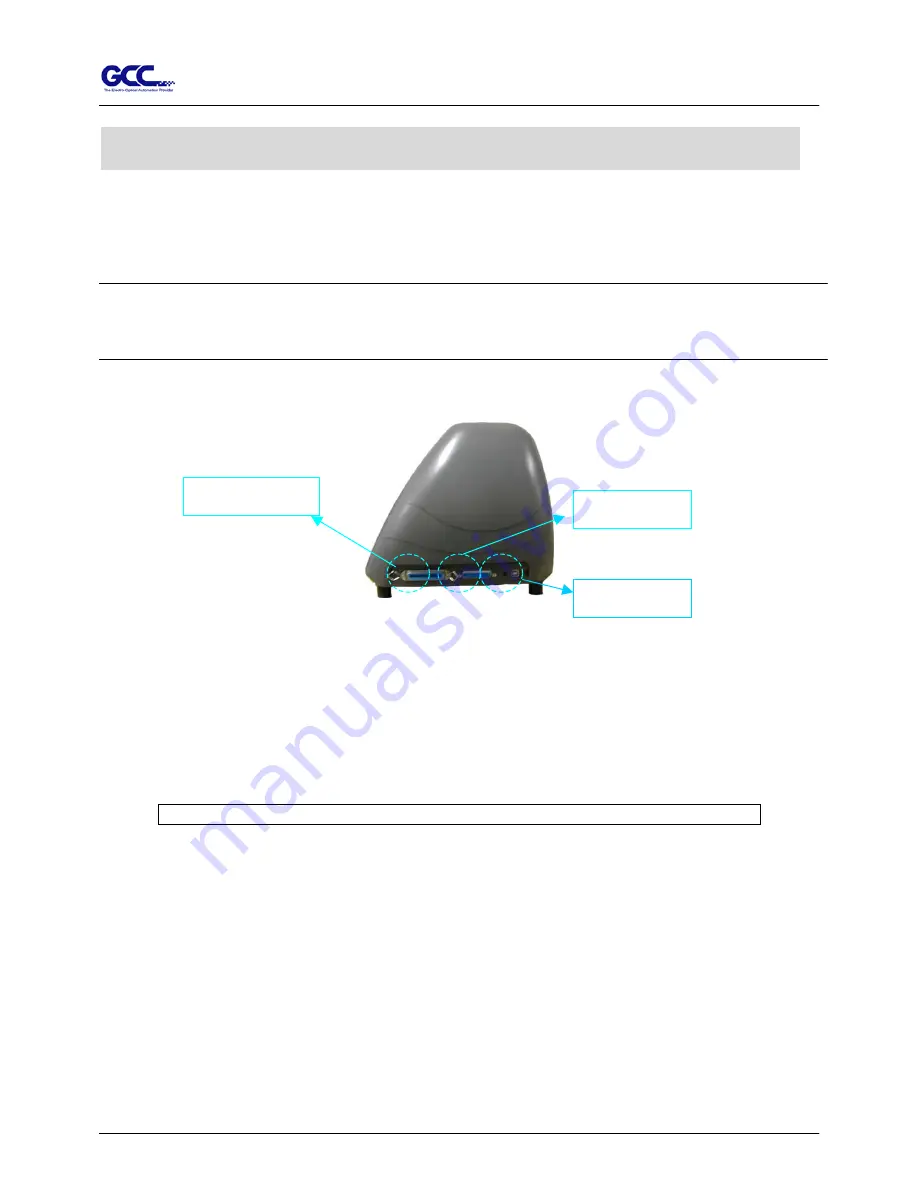
4. Making Connections                                           

The cutting plotter communicates with a computer through a 

USB (Universal Serial Bus), Parallel port


(Centronics) or 

Serial port


(RS-232C)

. This chapter shows you how to connect the cutting plotter to a 

host computer and how to set up the computer/cutting plotter interconnection. 
 
!! 

Notice:

 When USB connection is enabled, both parallel port and serial port will be disabled 

automatically.  


USB port 

Serial port 

Parallel port   

Figure 3-1 

4.1 Universal serial bus 

Puma II build-in USB interface are based on the Universal Serial Bus Specifications Revision 
1.1. Operation system of Windows 95, Windows NT don’t support USB.   
 
4.1.1 USB driver installation 

Caution!! Don’t plug USB cable into Jaguar II before you install USB driver. 

a. Put USB cable aside (don’t plug it into Jaguar II). 
b. Insert “Installation CD”, and then click on “USB driver” to install USB driver. When it 

shows “USB Driver installed”.   


4.1.2 Connection 
Plug the USB cable into the Jaguar II USB interface connector. Plug the other end of the cable 
into the PC’s USB interface connector. 
 
4.1.3 Cutting driver or sign cutting software installation   
Insert “Installation CD”, and then click on “Driver” to install driver working with CorelDraw.


Connecting Cutting Plotters                                            4-1 


Содержание Jaguar II JII-61

Страница 1: ...User Manual Great Computer Corporation V2 2003 7 3...

Страница 2: ...ration do not touch any of the moving parts of this machine such as the carriage Also be careful that clothing and hair do not become caught Always connect the power cable to a grounded outlet Always...

Страница 3: ...sec Tool up speed 45 60 cm sec Smooth cut DisableCutting Quality Small Letter HOW TO MAKE A LONG PLOT When you are making a long plot with a roll of heavy and wide vinyl paper you need to use AUTO UNR...

Страница 4: ...to secure the roll media 6 The protrusion length of the blade should be longer than the thickness of the vinyl Please see in the section of ABOUT THE TOOL After you notice all above then you ll enjoy...

Страница 5: ...same time as the pictures shown below CORRECT INCORRECT Press down DISABLE ENABLE Pull up bottom release Press down Stop Note In case the grips clipped together due to your wrong operation please use...

Страница 6: ...KEY OFFSET_KEY MISC KEY TOOL_SELECT_KEY and also the ARROW_KEYs Cutting test Press CUT TEST position carriage by arrow keys ENTER Speed Force Offset Press related key to adjust then repeat the step of...

Страница 7: ...lective vinyl cardboard sandblast and stencil sharp edge BK07028A BK07028A BK07028A BK07028A GCB GCB GCB GCB 360SB 360SB 360SB 360SB The blade is 60 with Green Cap Green Cap Green Cap Green Cap 0 50 m...

Страница 8: ...g to the reference point OFFSET is the distance that the blade tip is displaced from the centerline of the blade Protrusion Length of the Blade Length of protrusion t1 t 2 2 but for your convenience y...

Страница 9: ...ade Installation 2 7 2 5 Media Loading 2 9 2 5 1 Loading the Sheet Media 2 9 2 5 2 Loading the Roll Media 2 10 2 6 Tracking Performance 2 13 2 7 Adjusting the Cutting Force and Offset 2 14 3 Descripti...

Страница 10: ...Jaguar II User Manual Table of Contents 6 3 Cutting Plotter Computer Communication Problems 6 3 6 4 Software Problem 6 4 6 5 Cutting Quality Problem 6 5 Appendix Specification...

Страница 11: ...2 pieces 1 set of Roll Holder Guide Bushes 4 pieces 1 set of Roll Holder Support 2 pieces 24 pieces of M6 screws 1 piece of M5 L shape hexagon screw driver 1 piece of M6 L shape hexagon screw driver 4...

Страница 12: ...hile performing cutting SliterGroove sheets off the extra media easily along this groove Grid Drums move the media back and forth during operation Alignment Rulers Media can be aligned with the clear...

Страница 13: ...body Roll Holder Support supports roll holders Stand Beam stabilizes th Stand Supports the cutting plotter body Roll Holder Guide Bushes Serve to keep the roll media in place when media is pulled from...

Страница 14: ...Side of Jaguar Figure 1 5 Figure 1 5 USB Connector used to connect the cutting plotter to a computer through a USB cable Serial Interface Connector RS232C used to connect the cutting plotter to a comp...

Страница 15: ...emporarily halts cutting in process or continues ON OFF LINE Key used to stop the cutting job or aborting the change of the setting Cut Test Key executes a cutting test for verifying the blade force a...

Страница 16: ...ce for the machine accessories and supplies Keep the working area stable avoiding sever vibration Keep the temperature between 5 and 40 41 104o F in the workshop Keep the relative humidity between 30...

Страница 17: ...screw driver 1 piece of M5 L shape hexagon screw driver 24 pieces of M6 screws 4 pieces of hold plugs Step 2 Remove the plotter body and the accessories from the shipped carton Place the stands uprigh...

Страница 18: ...m the carton Position your stand under the plotter and then insert the screws into the holes on plotter s bottom and tighten them up as shown in Figure 2 5 Step 6 Insert the roll holder support with t...

Страница 19: ...ation of Sign Cutting Plotter 2 4 Step 7 Place two roll holders into the holes in the roll holder support Figure 2 7 Step 8 Lastly the complete picture will be shown like below see Figure 2 8 Roll hol...

Страница 20: ...s 1 piece of M4 L shape hexagon screw driver 1 piece of M5 L shape hexagon screw driver 1 piece of M6 L shape hexagon screw driver for adjusting the screws of Roll Holders Step 2 Put the 4 Plastic Foo...

Страница 21: ...insert the M6 screws into the holes of Roll Holder support assembly and tighten them with M5 L shape screwdriver Like Figure 2 3 3 Step 5 Place the 2 roll holders into the holes of Roll Holder Suppor...

Страница 22: ...blade holder Insert a blade into the bottom of the blade holder and remove the blade by pushing the pin Make sure that your fingers are away from the blade tip Step 1 Install blade Figure 2 11 Step 2...

Страница 23: ...lose its sharpness after a period of usage the cutting quality might be affected By increasing the cutting force it might do the trick However once the blade is worn out and no longer provides a relia...

Страница 24: ...side or the backside The color alignment rulers on the platen extension will help you to adjust the media precisely Step 3 Then move the pinch rollers manually to the proper position Be sure the pinc...

Страница 25: ...plotting cutter begins to work Note 1 Always adjust the position with the pinch roller raised 2 Move the pinch roller by applying force at the rear portion of the pinch roller support 3 Do not move it...

Страница 26: ...end of each roll media and tighten the thumbscrew until the roll media is firmly gripped see Figure 2 23 Then put the roll media on the roll holders Adjust the position of the roll media ensure that...

Страница 27: ...rums 6 Push the lever backward to lower down the pinch rollers 7 Fixes roll media guide bushes on the roll holder to secure the roll media 8 Turn on the power switch the tool carriage will sizing the...

Страница 28: ...as follows 1 If the media length is less than 4 m leave the margin of 0 5mm 25mm in the left and right edges of the media see Figure 2 27 2 If the media length is greater than 4m leave at least 25mm...

Страница 29: ...same time the new origin is also set at the cutting test position When the cutting test is completed a pattern appears Peel off the pattern to see if it can be easily separated from the media base If...

Страница 30: ...e tu p R e s u m e P A U S E F o rc e 8 0 g f O K E N T E R F o rc e k e y J a g u a r II in p ro c e s s in g U s e to s e le c t U s e to s e le c t E N T E R to e n a b le th e s e ttin g O ffs e t...

Страница 31: ...Scale Length Select OK Enter Scale W idth Select OK Enter 1S 72 F 80 O 0 275 M Select OK Enter Set Smoothing Cut Select OK Enter Set Tangetial Mode Select OK Enter Pouncing 0 00mm Select OK Enter Pane...

Страница 32: ...y When cutting small letter set it to Small letter When cutting at very fast speed please set it to Draft For normal operation please set it to Normal Draft Fair Normal Fine Small Letter Normal Force...

Страница 33: ...ngth of the rolled media is less than 2 meters or the rolled media is light it is recommend to set this as Disabled Auto unroll is only effect on the roll edge media Using Single mode to size paper wi...

Страница 34: ...19200pbs 7 Bits with ODD Parity 19200 e 7 1 p 19200pbs 7 Bits with EVEN Parity 19200 n 8 1 p 19200pbs 8 Bits with NO Parity 19200 o 8 1 p 19200pbs 8 Bits with ODD Parity 19200 e 8 1 p 19200pbs 8 Bits...

Страница 35: ...anges the values to the actual length Set Smoothing Cut Enable this feature to make curves smoother Set Tangential Mode Provide the emulation tangential cutting technique with thicker media types and...

Страница 36: ...est at the present blade position For more information please refer to 2 7 adjusting the blade force and cutting speed Recut Copy Allows user to repeat the last job without sending the file again Sett...

Страница 37: ...are based on the Universal Serial Bus Specifications Revision 1 1 Operation system of Windows 95 Windows NT don t support USB 4 1 1 USB driver installation Caution Don t plug USB cable into Jaguar II...

Страница 38: ...cription 4 3 2Transmitting the Data to Plotter There are two options to transmit the data from the computer to the cutting plotter Option 1 With proper interface settings the data can be transmitted f...

Страница 39: ...rompt via serial connection However values in a MODE command should comply with the related requirements of your software Refer to DOS manual for further information 4 4 Interface of Macintosh Compute...

Страница 40: ...ck Never use solvents abrasive cleaners or strong detergents for cleaning They may damage the surface of the cutting plotter and the moving parts Recommended Methods Gently wipe the cutting plotter su...

Страница 41: ...e the drum manually while cleaning Refer to Figure 5 1 Figure 5 1 5 3 Cleaning the Pinch Rollers 1 If the pinch rollers need a thorough cleaning use a lint free cloth or cotton swab to wipe away the a...

Страница 42: ...r connector properly Does the power LED still illuminate Solutions If the LCM is able to display the message the cutting plotter should be in a normal condition Switch off the cutting plotter and turn...

Страница 43: ...ng well and if the media is well loaded Correct the problem and re power on to reboot system Error Check Media Or Y Motor This message indicates that there might be an obstruction to carriage relating...

Страница 44: ...ng plotter and computer If it still does not work have your cutting plotter serviced No Refer to the MISC key in Chapter 3 Description of Operation for the port setup Is the connection cable connected...

Страница 45: ...d using a different cable Does the software vendor provide a sample file Most well known cutting softwares in the world have drivers for our cutting plotters If not use software that has HP GL and HP...

Страница 46: ...force set up properly The default for tool force is 80 gf Yes No Adjust the tool force to obtain an optimum blade force Refer to chapter 3 FORCE and CUTTING TEST Is the tool offset set up properly Yes...

Страница 47: ...oftware Resolution 0 025 mm Repeatability 0 1mm Buffer Size 4 MB Interfaces USB Parallel and Serial RS 232C Commands HP GL HP GL 2 Configurable Origin Yes Curve Arc Smoothing Yes Test Cut capability Y...

Отзывы:

Похожие инструкции для Jaguar II JII-61