


IS400 machine
. 34
First contact
Adjusting the machine
After it has been used for some while the reference point of the machine can alter slightly (the centre of the engraving area
of the machine is slightly out of line with the clamping system, the Z position at the mechanical stop is above or below its
normal position).
The IS400 machine has a very simple adjustment system which can be carried out by the user (which enables the machine
to be adjusted without having to return it to the distributor).
If you notice that it is out of line in relation to your engraving measurements, adjust the machine.
To adjust the machine
1.
Switch on the IS400 machine
.
<<GRAVOGRAPH>>
- VERSION xx.xx -
2.
When this message is displayed press
SPINDLE ORIG. ADJUST
to confirm
3.
Take off the jigs
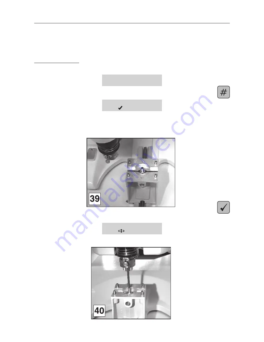
4.
Put the cutter button between the jaws of the vice and tighten using the tightening button
(diagram 39).
5.
Validate
The tool-holder moves towards the centre of the vice (
diagram 40
).
SPINDLE ORIG. ADJUST
to modify
6.
Place the cutter into the spindle (diagram 40). It should easily slide into the cutter button.


