background image


11 

Installing the rudder and elevator horns 

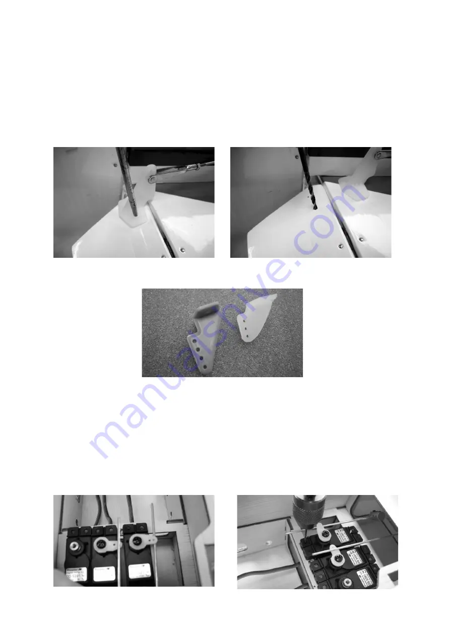
Screw an M2 locknut and a clevis onto the threaded end of each rudder and elevator 
pushrod.  Slip  the  pushrods  into  the  plastic  guide  tubes  and  connect  the  clevises  to 
the horns. 
 
The horns should be positioned on the control surfaces in such a way that the clevis 
linkage  hole  lines  up  exactly  with  the  hinge  pivot  axis.  Drill  holes  for  the  retaining 
screws in the control surfaces.  

 
Note that the rudder horn has to be modified to the shape shown in the photo below. 


With the horns in place, file the projecting screw ends flush with the spreader plate. 
 
The  rudder  and  elevator  servos  must  now  be  centred  accurately:  connect  the 
receiving system, switch the transmitter on and check that the associated trims are at 
centre. 
 
Install  the  servos  in  the  servo  plate,  positioned  in  such  a  way  that  the  pushrods 
coincide exactly with the linkage holes in the servo output arms. Drill 1.5 mm Ø pilot-
holes  for  the  servo  retaining  screws,  then  fix  the  servos  in  this  position  using  the 
screws supplied in the accessory packs. 


Содержание TAXI SPORT II

Страница 1: ...For two stroke engines of around 7 46 cc capacity and electric motors This model requires a four function radio control system GRAUPNER GmbH Co KG D 73230 KIRCHHEIM TECK GERMANY Modifications reserve...

Страница 2: ...relative beginner to this type of model flying we recommend that you enlist an experienced model pilot to help you check and test fly the model RC system components and the control surface linkages mu...

Страница 3: ...ing loose just squirt white glue into the hole before fitting the screw Additional accessories required Power plant and accessories Engine Order No Propeller Order No Silencer Order No OS MAX 46 AX 7...

Страница 4: ...ded Synthetic oil based fuel to suit engine Fuel filter e g Order No 1650 1 Fuel tubing e g Order No 1643 Manual fuel pump e g Order No 1610 Glowplug battery with glow clip e g Order No 3253 Electric...

Страница 5: ...ers with the flange on the underside The spacers are easier to fit if you slip them onto a suitable screwdriver first Connect the appropriate extension cable to the servo lead and fit a heat shrink sl...

Страница 6: ...that the servos do not need to be reversed this may be useful if you are using a simple non computer RC system Place a setsquare on the wing as shown in the photo and mark the position of the servo ou...

Страница 7: ...them Snip off excess screw length using side cutters before filing back the cut ends flush with the spreader plate Locate the M2 threaded pushrod 180 mm long and fit a locknut and clevis on the threa...

Страница 8: ...at the iron should be a low wattage type the heat should be just enough to melt the film Locate the slots with your fingertips and mark their outlines with a felt tip pen Pierce the film with the tip...

Страница 9: ...oll white glue or UHU hart cellulose cement Position the panels exactly as described above align them carefully and tape them in place Note that the fin must be at right angles to the tailplane Allow...

Страница 10: ...hed to the bottom of the rudder so that movement of the rudder is transferred to the tailwheel Fit the plastic lug on the projecting wire and fix it to the rudder using a single pan head screw Use a p...

Страница 11: ...Note that the rudder horn has to be modified to the shape shown in the photo below With the horns in place file the projecting screw ends flush with the spreader plate The rudder and elevator servos m...

Страница 12: ...nector before connecting the unit to the elevator servo using a short pushrod attached to the central hole As described for the aileron servos bend the pushrods at right angles at the marked point cut...

Страница 13: ...ed squarely on the mount arms The distance between the firewall and the front face of the propeller driver should be 113 mm You can now mark the position of the holes for the engine mount on the firew...

Страница 14: ...or jamming when the stopper is in place Push the tank stopper complete with pick up and pre formed tubes into the throat of the fueltank Note that one tube must face down for filling the tank The tube...

Страница 15: ...Please note that fuel will run out of the overflow pressure line when the tank is full Take care not to fill the silencer with fuel The cowl can now be fitted along with the propeller and the spinner...

Страница 16: ...Mark the position of the fixing screw holes on the firewall to suit the motor mount you intend to use and drill holes in the firewall at the marked points to suit the retaining screws The electric mot...

Страница 17: ...receiver battery in foam and secure it in the fuselage in such a way that it cannot possibly shift Connect the two aileron servos to the extension leads then connect the wing panels using the alumini...

Страница 18: ...avel and are not obstructed mechanically at any point When you move the rudder stick to the right the rudder should also deflect to the right left stick left rudder Pull the elevator stick back toward...

Страница 19: ...del is prohibited A radio controlled model aircraft can only work properly and fulfil your expectations if it is built very carefully and in accordance with the building instructions Do not make any m...

Страница 20: ...his is extremely dangerous If there are passers by or spectators at your flying site make sure that they are aware of the dangers inherent in your activity and insist that they keep a safe distance aw...

Страница 21: ...k wooden dowel with a piece of water hose pushed over it Many model engines are very noisy producing a sound level much higher than 85 dB A which implies that you should wear ear defenders Never run a...

Страница 22: ...or spinner All model flyers should behave in a manner which minimises the danger to people and property Never act in any way which will disturb other flyers and jeopardise safe orderly flying at the...

Страница 23: ...lly paid for the model This model is built and flown at the sole and express responsibility of the operator The only way to avoid injury to persons and damage to property is to handle and operate the...

Страница 24: ...them They may be seriously damaged if they are free to slide about Care and maintenance Clean the model carefully after every flight and remove any dirt from the propeller Clean the aeroplane and the...

Отзывы: