GRAUPNER SEA FURY 9354 Скачать руководство пользователя страница 8

GRAUPNER GmbH & Co. KG D-73230 KIRCHHEIM/TECK GERMANY 

We reserve the right to introduce modifications. Not liable for printing errors! 


       01/2012 

    Made in 

Vietnam


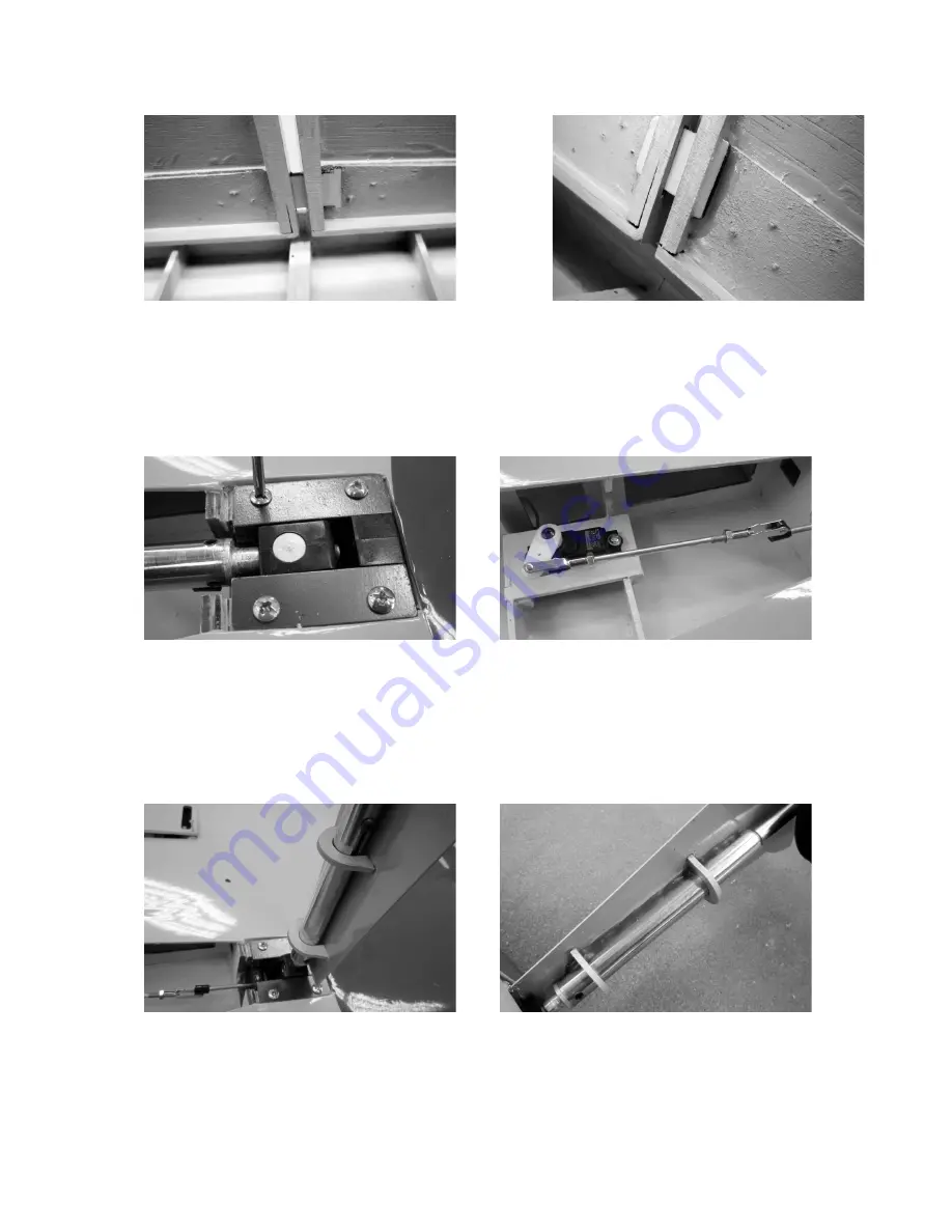
The two-part landing flaps are connected using the GRP connector. As shown in the 
photos, slide in the connectors and glue them into a flap. 
 
Installation of the landing gear 
As  shown  on  the  photos,  install  the  landing  gear  in  the  wing  using  the  four  sheet 
metal  screws;  likewise  for  the  servos.  For  the  attachment  screws,  pre-drill  a  pilot 
hole. 

 
The steering linkages must be adjusted so that the retractable undercarriage can be 
locked in the extended and retracted positions. 
Now the landing gear covers can be installed / glued on. As a test, place the covers 
onto  the  landing  gear  legs,  glue  on  with  a  few  drops  of  fast  setting  glue,  and  align 
them  while  in  the  retracted  position.  Now  extend  the  landing  gear  again  and  glue 
them onto the legs of the landing gear using Stabilit Express. 


Now the wheels can be attached using the wheel axles. 

Содержание SEA FURY 9354

Страница 1: ...right to introduce modifications Not liable for printing errors 01 2012 Made in Vietnam 1 Re Order No 9354 Assembly instructions SEA FURY For two stroke motors up to about 20 cm displacement and Elec...

Страница 2: ...model aircraft it is best to ask an experienced person to help you with the pre flight check and during the first few flights RC parts and rudder linkages are built in during assembly as per the corre...

Страница 3: ...o keep them from loosening Squirt casein glue into the drill hole and screw in the screw All metal bolts and nuts should be secured against loosening with thread lock fluid such as UHU schraubensicher...

Страница 4: ...er and battery for example cellular cauoutchouc rubber Order No 1637 is needed Adhesives Casein glue such as UHU coll Order No 958 60 UHU hart such as Order No 534 35 Fast setting glue such as Order N...

Страница 5: ...ng the receiver system Fasten the servo to the attachment block using the screws included with the servos To do so insert the rubber grommets with the brass hollow rivets collar downward into the serv...

Страница 6: ...s are again fastened in the wing halves with the screws included Using sandpaper or sanding block sand the control horns on the surfaces to be glued in order to achieve an adequate connection when glu...

Страница 7: ...in the photo countersink the drill holes in the landing gear hinges Fasten the landing gear to the wings using the hinges Now the rudder linkages are prepared Adjust the length of the linkages so that...

Страница 8: ...the four sheet metal screws likewise for the servos For the attachment screws pre drill a pilot hole The steering linkages must be adjusted so that the retractable undercarriage can be locked in the...

Страница 9: ...eering lever Secure the attachment screw of the steering level with UHU schraubensicher thread lock fluid Cut the cover to fit precisely and glue it to the fuselage with transparent adhesive film Inst...

Страница 10: ...are also in neutral position The throttle rod is adjusted so that the carburettor is half open when the servo is in centre position Depending on the motor used the necessary cut outs for the cylinder...

Страница 11: ...11 Unscrew the Allen screws then push up the engine bonnet so that it moves under the strips and the spinner base plate is about 1 5 2 mm from the engine bonnet In this position mark the four attachme...

Страница 12: ...ilips head screw to fasten the stopper in place It is important to tighten the screw so that the tank is completely sealed This can be checked by holding the tank under water Hold it under water and b...

Страница 13: ...rside of the tail fin Use a hot soldering iron to melt through the covering sheet somewhat smaller than drawn Make sure the soldering iron used is too hot the heat should be just enough to melt the sh...

Страница 14: ...ace as shown in the photo Experience has shown that the pilot figure can be secured using double sided tape Order No 2904 The head rest can be glued on using UHU ALLESKLEBER Kraft all purpose adhesive...

Страница 15: ...ned firmly to the fuselage Place the fuselage cover onto the fuselage opening so that the two pegs fit into the holes in the bulkhead The fuselage cover is fastened by snapping the two spring loaded l...

Страница 16: ...notes are part of these instructions and must be stored carefully with the operating instructions and if the model is passed on to others they must also be passed on to the next user Motorised models...

Страница 17: ...the safe operation of your model and motor Questions regarding the safe operation of model and motor can be answered by your retailer Propellers and all rotating parts that are powered by a motor pose...

Страница 18: ...emanates from the exhaust pipe but also very hot liquid combustion residue which can result in burns After operation remove residual fuel from the tank and motor Every time you intend to operate your...

Страница 19: ...s squares school playgrounds parks or sports grounds et cetera and ensure that you are always in full control of the model To ensure that you can stop your engine at any time the throttle must be adju...

Страница 20: ...e to loss of business or turnover interruption of business or other direct or indirect consequent damage stemming from the operation of the model is excluded The total liability in all cases and under...

Страница 21: ...d or to dirt Protect the model and RC equipment against damage or slippage during transport Care and maintenance Clean the model carefully after each use Also remove any dirt from the propeller Clean...

Отзывы: