54
KAM-SD-2AES-MUX Instruction Manual
KAM-SD-2AES-MUX Links and Web Pages
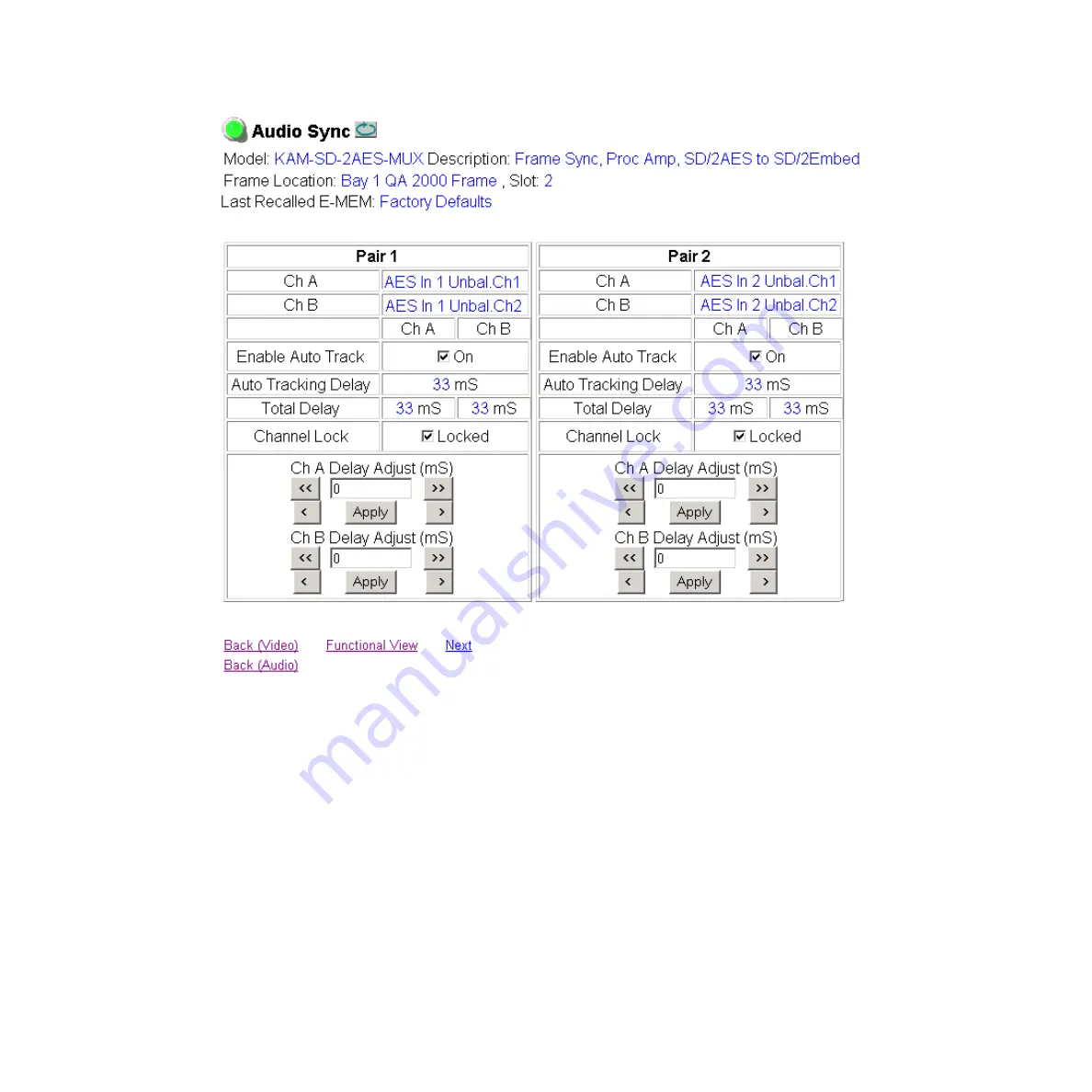
Figure 34. Audio Synchronizer Web Page
Страница 1: ...KAM SD 2AES MUX KAMELEON SERIES MODULES Instruction Manual SOFTWARE VERSION 4 0 1 071834800 DECEMBER 2004 ...
Страница 2: ...ase Solutions to problems and troubleshooting efforts can be found by searching our Frequently Asked Questions FAQ database Software Downloads Software updates drivers and patches can be down loaded Region Voice Fax Address Web Site North America 800 547 8949 Support 530 478 4148 Sales 530 478 3347 Support 530 478 3181 Grass Valley P O Box 599000 Nevada City CA 95959 7900 USA www thomsongrassvalle...
Страница 3: ...nterface 19 Web Page Operations and Functional Elements 21 Status and Identification Header 21 Initial Configuration Process Overview 23 KAM SD 2AES MUX Links and Web Pages 24 Status Web Page 25 Color coded Status Indicators and Links 25 Status Front Module Properties 25 Submodule Properties 25 Warning Fault Summary 27 Input Output Configuration Web Page 28 Web Page Elements 29 Functional View Web...
Страница 4: ...eb Page 52 Audio Sync Web Page 53 Enable Auto Track 53 Delay Adjustments 53 Audio Processing Web Page 55 Audio Gain 55 Output Processing 55 E MEM Configuration Web Page 57 File Operations 59 Slot Configuration 62 Slot Identification 62 Locate Module 62 Slot Memory 62 Frame Heath Reporting 64 Hardware Switch Controls 64 Slot SNMP Trap Reports 64 Software Update Web Page 65 Specifications 66 Service...
Страница 5: ... the Kameleon multi function modules that are part of the Kameleon Media Processing System As part of this module family it is subject to Safety and Regulatory Compliance described in the Kameleon 2000 Series frame and power supply documen tation see the Kameleon 2000 Series Frames Instruction Manual ...
Страница 6: ...6 KAM SD 2AES MUX Instruction Manual About This Manual ...
Страница 7: ...ut stream Audio and video delay synchronization and processing amplifier Powerful line by line VBI processing including user configuration of active video lines for carrying data Built in 4x4 audio router for mapping audio channels to specific AES streams Audio and video test generators Hot swappable 5 user programmable E MEM registers Save load module configuration files to a networked PC SNMP mo...
Страница 8: ...components 2000NET module software version 3 2 2 or later recommended for full functionality 2000GEN module Dual 130W power supplies in the 2000T1DNG frame Single 240W power supply and 2000FAN in the 2000T3NG frame Frame Capacity The 1 RU 2000T1DNG with dual 130W power supplies 2000NET and 2000GEN modules frames have no Kameleon module capacity limitations The 3 RU 2000T3NG single 240W p s 2000FAN...
Страница 9: ...e that can be plugged into any of the 12 frame slot pairs The rear modules provide the input and output interface connectors Installing the Front and Rear Modules To install a KAM SD 2AES MUX module set in the 2000 Series frame 1 Locate a vacant slot in the rear of the 3 RU frame Figure 1 Figure 1 2000T3NG Kameleon Frame Rear View Mid frame motherboard with power and communication buses Front rear...
Страница 10: ...Verify that the module connector seats properly against the midplane 4 Using a crossblade screwdriver tighten the two screw locks to secure the module in the frame CVO SD0 AES 1 SIG J10 J9 J6 J5 J4 J3 J1 V1 J2 2900 PRM 7 J11 AES 2 AES 1 AES 2 J8 J7 AES 3 AES 4 AES 3 AES 4 Rear alignment post and receptacle Screw lock both sides 8345_01 2000 frame rear view KAM AES R module Board edge guides both s...
Страница 11: ...ont slot see Figure 4 7 Verify that the module connector seats properly against the midplane and rear module connector 8 Press firmly on both ejector tabs to seat the module Figure 4 Installing Front Media Module 2 3 4 5 6 7 8 9 10 11 12 15 13 1 8173 04 Network Slot 13 Reference Distribution Slot 15 Main Power Supply Slot 19 Secondary Power Supply Slot 21 Front Media Slots 1 12 Fan Sled Slot 20 Al...
Страница 12: ...n the Input Output Configuration Web Page on page 28 Connect balanced or unbalanced AES audio to the correct type of audio connectors shown in Figure 5 SDI Video Out The SDI video is output at BNC connector J1 labeled SDO Figure 5 KAM AES R Input Output Connectors 8348_01 CVO SD0 AES 1 SIG J10 J9 J6 J5 J4 J3 J1 SIG J2 2900 PRM 7 J11 AES 2 AES 1 AES 2 J8 J7 AES 3 AES 4 AES 3 AES 4 J11 VI SDI Video ...
Страница 13: ...D3 D4 D5 D6 D7 D8 PWR Green diagnostic LED on indicates power OK For factory use FAULT Red diagnostic LED is off during normal operation Ejector Tabs Processor Module Front Edge COMM Yellow LED on during remote control communication CONF Yellow LED on when module is initializing or processing control data GND Digital ground 8345_03 Signal Present green LED CVO SD0 AES 1 SIG J10 J9 J6 J5 J4 J3 J1 S...
Страница 14: ...ditions Indicated LED Indication Condition Fault red Off Normal operation On continuously Module has detected internal fault Long flash One of the inputs is missing or is wrong standard Short flash Errors present in SDI and or AES EBU input COMM yellow Off No activity on frame communication bus Three flash off pattern Module Location command received from a remote control system Short flash Activi...
Страница 15: ...o button N A Frame reference loss of signal report Enable Enable or Disable Video Input Select Frame Reference Loss of Signal checkbox N A SDI Input Error status Warn SDI Errors Warn SDI Errors or No Warning Video Input Select SDI Input Errors Warn SDI Errors Warn SDI Errors checkbox N A Select output timing source Video In Video In or Internal Frame Reference Video Input Select Output Timing Sele...
Страница 16: ... View Hue Phase control degrees ChroPhs Main video B Y gain 100 50 to 149 6 0 4 steps Video Proc Advanced View B Y Gain control BYGain Main video B Y balance offset 0 0 3 55 to 3 44 0 11 steps Video Proc Advanced View B Y Balance Offset control N A Main video R Y gain 100 50 to 149 6 0 4 steps Video Proc Advanced View R Y Gain control RYGain Main video R Y balance offset 0 0 3 55 to 3 44 0 11 step...
Страница 17: ...k or Unlocked Audio Sync Pair 1 and Pair 2 Ch A and Ch B Channel Lock Locked checkbox N A Audio Pair 1 Ch A delay adjust Audio Pair 1 Ch B delay adjust Audio Pair 2 Ch A delay adjust Audio Pair 2 Ch B delay adjust 0 0 to 5180 ms 20 ms steps Audio Sync Pair 1 and Pair 2 Ch A and Ch B Delay controls ms Ch1ADly Ch1BDly Ch2ADly Ch2BDly Select audio processing option for Pair 1 Ch A and Ch B and Pair 2...
Страница 18: ... channels that you can easily manipulate with user configured knobs Update software for applicable modules and assign frame and panel IP addresses with the NetConfig Networking application Recommended for real time control of module configuration parame ters providing the fastest response time Note Not all module functions are available with the control panel such as E MEM and factory default reca...
Страница 19: ...d processing time and a manual screen refresh to become effective Web interface recommended for setting up module signal and slot names E MEMS and reporting status for SNMP and monitoring Refer to the Frame Status page shown in Figure 8 on page 20 The Kame leon and 2000 modules can be addressed by clicking either on a specific module icon in the frame status display or on a module name or slot num...
Страница 20: ...he selected link s Status page is first displayed and the sub list of links for the selection is opened The sub list allows you to select a particular information page for the selected device Content display section displays the information page for the selected frame or module frame slot icons are also active links Refresh button for manual update of page ...
Страница 21: ...cal adjustment control has a Coarse adjust button left and right top double arrows and a Fine adjust button left and right bottom single arrows To change a value use the arrow button controls or enter a value into the number field and select the Apply button You may also enter a number into the number field from a keyboard and hit the Enter key to apply the value A Refresh button circular arrow is...
Страница 22: ... Faults are dis played LED colors indicate Green Pass no problems detected Yellow Configuration error warning Red Fault condition detected Variables Model and Description are read only generated by the module Frame Location is entered in 2000 Series Kameleon Frame configura tion Slot number reports the module s location in the frame Last Recalled E MEM reports the last E MEM configuration recalled...
Страница 23: ... signal presence and condition 3 Go to the Video Input Select web page to configure the video source and output timing source 4 Go to the MUX web page if you are multiplexing audio into the output video signal 5 Go to the Functional View web page to Verify the module s functional configuration is correct and Begin with the Input block links to configure each function in turn Note Next Functional V...
Страница 24: ...View shows a block diagram of the module with links to each configuration web page page 31 Module Configuration web pages for setting up the module beginning on page 32 E MEM provides a Standard view for Local Recall operations for up to 5 E MEM registers page 57 and an Advanced view providing addi tional Save to and Load from file operations page 58 Slot Config provides a Locate Module function S...
Страница 25: ...ule as indicated in Figure 11 on page 26 Arrows represent signal paths that may or may not be monitored These elements act as links when their function is active indicated by underlined function name Color code Green Pass operating as expected Yellow Warning signal is absent has errors or is misconfigured Red Fault a component has failed Grey Not monitored White Not present Status Front Module Pro...
Страница 26: ...26 KAM SD 2AES MUX Instruction Manual KAM SD 2AES MUX Links and Web Pages Figure 11 Module and Signal Status Warning and Fault summary section ...
Страница 27: ...Input is 525 and reference is 625 lines WARNING Video Input is 625 but configuration is 525 lines WARNING Video Input is 525 but configuration is 625 lines WARNING Video Input Signal not detected WARNING Frame Reference is not present WARNING Frame Reference is not locked to input WARNING Frame Reference is not present WARNING No Video output GenLock selected but not present WARNING 1 or more Audi...
Страница 28: ...gnal names that will help later in the config uration process Figure 12 illustrates the I O Config web page for the KAM AES R passive rear module required for the KAM SD 2AES MUX front module with unbalanced audio inputs selected Unbalanced radio button selected Note Only the selected AES inputs are valid Unconfigured AES inputs are invalid and should not be used Figure 12 KAM AES R Rear Module Co...
Страница 29: ...he top header row provides the connector hardware physical label J and the dedicated signal type for the connector This information is deter mined by the type of rear module and front processor module installed refer to the Functional View Web Page on page 31 Connectors The connector row illustrates connector type provided BNC or 3 pin ter minal for each port For this rear module one serial digita...
Страница 30: ...ws by color and signal type the signal status reports that may be displayed in the Status row for this module configuration Table 4 I O Config Status Report Messages Color Video In Analog Audio In Analog Audio Out Digital Audio In Digital Audio Out Video Out Green Present None None Present None None Yellow Not present or 525 625 mismatch None None Not Present None None Light Grey None None None No...
Страница 31: ...nctions and signal paths that are active or inactive in the current configuration It can be used as a link map for configuring module functions Begin configuring with one of the input function blocks on the left Color coding indicates active functions and flow Greyed components are inactive due to hardware and or software constraints Underlined module functions are links to the web page for that f...
Страница 32: ...r All Status button to clear and reset the status reporting Figure 15 SDI In Web Page Summary View To view a detailed view of the SDI input status select the Detail radio button to bring up the view shown in Figure 16 on page 33 This view provides input signal status for both EDH Error and Feed Forward status Each status report can be disabled by deselecting the cor responding Reporting checkbox E...
Страница 33: ...KAM SD 2AES MUX Instruction Manual 33 KAM SD 2AES MUX Links and Web Pages Figure 16 SDI In Web Page Detail View ...
Страница 34: ...in the Video Selection section in both the Standard and Advanced views Input Name read only signal name is entered on the I O Config web page Input Status Signal presence reported Enable disable Loss of Signal report to both Kameleon status web pages and SNMP monitoring devices Note The disabling of video and reference Loss of Signal reports and SDI Input Error warnings allow you to filter reports...
Страница 35: ...vided from the 2000GEN module Frame Delay mode is reported when the input signal Video In is used for timing reference Output Timing Selection The 2000GEN reference module must be installed in the frame and for the Kameleon to work as a frame synchronizer set the output timing source to Internal Frame Reference Otherwise set the output timing source to Video In Figure 17 Video Input Select Standar...
Страница 36: ...ced View Selection The VBI Data Lines panel will appear at the bottom of the web page see Figure 19 on page 37 for 525 line rate and Figure 20 on page 37 for 625 line rate 2 Select the last line includes all previous active video lines that will be used for data Selected active video lines will be shown in the Reserved for Data section of the web page as shown for lines 21 284 and 22 285 in Figure...
Страница 37: ...KAM SD 2AES MUX Instruction Manual 37 KAM SD 2AES MUX Links and Web Pages Figure 19 Advanced VBI Configuration 525 Line Rate Figure 20 Advanced VBI Configuration 625 Line Rate ...
Страница 38: ...eo In output timing reference Freeze Mode allows you to manually freeze the output using Field 1 Field 2 or one Frame Figure 21 on page 39 A field freeze provides less resolution and no motion artifacts in the output In Frame mode the resolution is higher since both fields are present but the presentation of two fields can cause motion artifacts Frame Sync mode using the 2000GEN Internal Frame Ref...
Страница 39: ...KAM SD 2AES MUX Instruction Manual 39 KAM SD 2AES MUX Links and Web Pages Figure 21 Frame Synchronizer Web Page Video In Reference Figure 22 Frame Synchronizer Web Page Internal Frame Reference ...
Страница 40: ...the internally generated 100 vertical color bars test signal Two modes of video processing are available Standard or Advanced With Standard selected only the Y Channel Video Processing controls on the left will be visible along with the clipping controls When Advanced is selected the B Y and R Y Gain and Balance Offset con trols will also be displayed as shown in Figure 24 on page 43 Standard View...
Страница 41: ...KAM SD 2AES MUX Instruction Manual 41 KAM SD 2AES MUX Links and Web Pages Figure 23 Video Processing Web Page Standard View ...
Страница 42: ...lso apply the clip levels to the vertical blanking interval by checking the Apply clips to VBI box This control is also available on the VBI SDI web page page 49 Use the following clipping controls to adjust levels on the video output Use the Soft Y White Clip control to set the clipping level for the top end white of the luminance signal positive excursions Use the Soft Y Black Clip control to se...
Страница 43: ...KAM SD 2AES MUX Instruction Manual 43 KAM SD 2AES MUX Links and Web Pages Figure 24 Video Processing Web Page Advanced View ...
Страница 44: ...ps and one or more groups are inserted or replaced all input Groups after the gap will be removed Figure 25 depicts the multiplexing of the processed audio streams into the SDI video output stream based on the selections made on the Mux web page in Figure 28 on page 47 Figure 25 Multiplexing into the SDI Stream The Mux web page provides two functions Group Deletion and Group Replacement Each of th...
Страница 45: ... appear under the Group Deletion section when any of the fol lowing conditions occur SDI Video In 525 line video format 24 bit audio format for Mux Group A or 24 bit audio format for Mux Group B An example of this may be seen in Figure 28 on page 47 Group Replacement The Group Replacement function allows the insertion of two processed AES audio streams from the external AES audio inputs determined...
Страница 46: ...Not Present and Output Status is Empty for each audio group No deletion is possible with this status Figure 26 No Embedded Audio Present Pass Embedded Audio If an embedded audio group is present in the incoming SDI signal and no replacement is selected the audio group will be passed to the output as shown in Figure 27 Input Status is Present and Output Status is Passed Check the corresponding Dele...
Страница 47: ... SDI stream with the Group replacement function as shown in Figure 28 In this case the present audio Group 1 has been replaced with Group 1 from the external AES audio input When Stream A and or Stream B is selected in the Replace column the Input Status will report Present and the Output Status will report Replaced Deletion is not possible with this status N A Figure 28 Multiplex Web Page ...
Страница 48: ...DI input stream with the Group replacement function as shown in Figure 29 In this case an external AES audio has been processed in the Audio processor and selected to replace an empty audio Group When Stream A and or Stream B is selected in the Replace column the Output Status will report Inserted in an empty Group selected in Group Replacement Figure 29 Insert Embedded Audio ...
Страница 49: ...ith the 525 or 625 radio button On a line by line basis you can blank existing VBI and Data Line infor mation by selecting the corresponding checkbox Check the Apply Clips to VBI checkbox to apply the clip values made with the Video Processor to all of the VBI lines This control is also available on the Video Processing web page page 40 Note The data lines not reserved for carrying data on the Vid...
Страница 50: ...50 KAM SD 2AES MUX Instruction Manual KAM SD 2AES MUX Links and Web Pages Figure 31 VBI SDI Web Page 625 Line Rate ...
Страница 51: ... Input characteristics reports the audio characteristics for input J9 and J10 as shown in the table Use the Clear button to reset the error detec tion Audio Stream Input reporting allows the user to enable or disable the fol lowing reporting items with the corresponding checkbox Sample Rate Conversion Loss of Signal to both Kameleon Status web page and SNMP mon itoring devices AES Errors Figure 32...
Страница 52: ...dio input channels and the columns rep resent the audio output channels The columns are grouped together into two different pairs Pair 1 Ch A and Ch B and Pair 2 Ch A and Ch B The streams in each pair are grouped together into a Mux group on the Mux web page Then Stream A or Stream B or both can be inserted into the SDI output video see MUX Web Page on page 44 Note Audio input names are assigned u...
Страница 53: ... frame sync The amount of auto tracking applied is shown in the Auto Tracking Delay read only display The total amount of delay is reported in the Total Delay read only display for each channel Delay Adjustments Each audio channel can be adjusted for delay separately or in pairs Use the following adjustments for audio delay To lock the two channels in a pair together select the Channel Lock checkb...
Страница 54: ...54 KAM SD 2AES MUX Instruction Manual KAM SD 2AES MUX Links and Web Pages Figure 34 Audio Synchronizer Web Page ...
Страница 55: ... or Pair 2 Adjust the gain 40 to 6 dB for each channel with the Ch A Gain Adjust and Ch B Gain adjust controls for each pair If the pair is locked adjusting either control will set the gain to the same value for each channel in the pair Note After gain has been adjusted a straight quote mark will be added to Ch A and Ch B to indicate the status of the channels after gain Output Processing Set the ...
Страница 56: ...56 KAM SD 2AES MUX Instruction Manual KAM SD 2AES MUX Links and Web Pages Figure 35 Audio Processing Web Page ...
Страница 57: ... such as the signal inputs select the Recall factory names button There are two E MEM view selections Standard and Advanced In Standard view Figure 36 any one of five learned E MEMs can be recalled by selecting the corresponding Recall button in the Local Opera tions window This will place the configuration for the entire module into that E MEM into the KAM SD 2AES MUX This change will occur imme ...
Страница 58: ...from To learn an E MEM 1 Open the Advanced view 2 When the configuration is complete for all channels on the module type a descriptive name for the configuration into an unused E MEM register or overwrite an existing one 3 Learn the E MEM to memory by selecting the corresponding Learn button All channel configurations are learned at once and stored in the same register This register is now learned...
Страница 59: ...urations to a computer hard drive or other accessible media for later recall to the onboard E MEM registers of any Kameleon module in your system To save to a file first make sure you have learned the configuration then press the Save To button This will bring up a File Download screen similar to Figure 38 Select Save Figure 38 File Download Screen ...
Страница 60: ...lect Save This E MEM reg ister is now saved to the selected location and may be recalled as described below Figure 39 Save As Screen Load File A file may be loaded from a saved directory to a register on the E MEM web page by selecting the Load From button in the associated E MEM reg ister in the Advanced view This will bring up the Load E MEM web page Figure 40 Figure 40 Load E MEM Web Page ...
Страница 61: ...to download and select Open Figure 41 Choose File Screen This will place the path and filename in the Load E MEM screen Figure 40 on page 60 If this is the correct file select Load Continue to load files or select Cancel to return to the main E MEM web page Loaded files will now be entered in the associated E MEM registers Select the associated Recall button for each E MEM register to load the con...
Страница 62: ...onfig inventory report Locate Module When enabled by selecting the Flash pulldown the Locate Module function flashes the yellow COMM and CONF LEDs on the front of the module to make it easy to locate in the frame see Operation Indicator LEDs on page 14 Slot Memory The slot configuration for each media module is automatically saved peri odically to the 2000NET module in that frame You may also sele...
Страница 63: ...KAM SD 2AES MUX Instruction Manual 63 KAM SD 2AES MUX Links and Web Pages Figure 42 Slot Configuration Web Page ...
Страница 64: ...llowing Slot SNMP Trap Reports to function Slot SNMP Trap Reports This section is displayed only when the SNMP Agent software has been installed on the 2000NET module refer to the 2000NET Instruction Manual for installation instructions Slot SNMP traps can be enabled only when the hardware switches for Module Fault reporting and Asynchronous Status reporting are enabled on the 2000NET module dipsw...
Страница 65: ...ibed in the 2000NET Instruction Manual available on line Software may also be updated using the NetConfig Networking Applica tion PC option available with Modular and other Grass Valley products as described in the documentation that accompanies the option Refer to the latest module Release Notes for complete details on how to obtain and install the latest software for this module Figure 43 Softwa...
Страница 66: ...694A SDI Output Number of outputs 1 Signal type Serial digital video conforming to SMPTE259M 10 bit 4 2 2 component digital signal Signal level 800 mV 10 Output impedance 75 Ω Connector type 75 Ω BNC on rear module DC offset 0 5 V when terminated into 75 Ω Output return loss 15 dB up to 270 MHz Jitter Conforms to SMPTE17 12 002 400 ps above 1 KHz Rise fall time 700 900 ps 20 80 amplitude SDI I O C...
Страница 67: ...z NA Differential voltage range 200 mV p p to 12 V p p 200 mV p p to 2 V p p Input return loss 25 dB 100 kHz to 6 MHz 15 dB 100 kHz to 6 MHz Sample rate 32 96 kHz 32 96 kHz Performance Static withstand 5 kV 330 Ω 150 pF Table 10 Multiplexing Specifications Parameter Value MUX Performance Standard SMPTE 272M A C Synchronous audio 48K 20 24 bits sample Compatible with buffer sizes down to 48 samples...
Страница 68: ...Invert L R L R L R 1 kHz 400 Hz Silence Individual setting for each channel Re pairing Complete flexibility to swap or recombine any input channel with any other Table 12 Electrical Length Specifications Parameter Value Electrical Length SDI In to SDI Out 1 line 10 µs AES EBU to SDI Out MUX 3 8 ms 48 kHz Table 13 Environmental Power Specifications Parameter Value Environmental Frame temperature ra...
Страница 69: ... Figure 44 Check for presence and quality of input signals Verify that source equipment is operating correctly Check cable connections Figure 44 Location of Module Fuse and Voltage Testpoints Refer to Figure 6 on page 13 for the location of PWR LED and Table 2 on page 14 for proper LED indications If the module is still not operating correctly replace it with a known good spare and return the faul...
Страница 70: ...70 KAM SD 2AES MUX Instruction Manual Service ...
Страница 71: ...le 17 web page controls 53 gain summary table 17 web page controls 55 group deletion web page control 44 group insertion Mux summary table 16 group replacement 44 web page control 45 multiplexing 44 multipliplexing conditions 46 processing summary table 17 web page controls 55 silence 52 sync 53 Audio Channel Pairing web page 52 Audio Proc web page 55 Audio Sync web page 53 auto tracking audio sum...
Страница 72: ...orting enabling and disabling 64 frame reference loss of signal reporting 15 summary table 15 web page control 34 frame sync summary table 15 web page controls 35 Frame Sync web page 38 freeze modes summary table 15 web page controls 38 frequently asked questions 2 front media module installation 11 Functional View overview 23 web page 31 fuse 69 G graphical user interface GUI 24 Grass Valley web ...
Страница 73: ...ntrol Panel control summary table 15 overview 18 O online documentation 2 output timing source summary table 15 web page control 35 outputs analog 66 D1 serial digital 66 HD 66 P power requirements 68 PWR LED 14 R Refresh button 21 removing modules 8 repair depot 69 R Y gain summary table 16 web page control 42 R Y offset summary table 16 web page control 42 S sample rate output summary table 16 w...
Страница 74: ...plying clips summary table 16 applying clips to VBI 42 blank VBI lines summary table 16 blanking 49 clipping summary table 16 reserving data lines 36 summary table 15 VBI SDI web page 49 vertical blanking interval VBI 34 vertical timing summary table 15 web page control 38 Video Gain Lock summary table 16 web page control 42 Video Input Select web page 34 video line rate summary table 15 web page ...