background image

48

8960ENC Instruction Manual

Status Monitoring


SNMP Reporting 

The Gecko 8900 Series system uses the Simple Network Monitoring Pro-
tocol (SNMP) internet standard for reporting status information to remote 
monitoring stations. When SNMP Agent software is installed on the 
8900NET module, enabled status reports are sent to an SNMP Manager 
such as the Grass Valley’s NetCentral application.

There are both hardware and software report enable switches for each 
report. Both must be enabled for the report to be sent. Software report 
switches are set on the 8900NET Configuration web page for the Frame, the 
8900NET module, and each module slot. Refer to the 8900NET Network 
Interface Instruction Manual for installation instructions. 

Содержание 8960ENC -

Страница 1: ...8960ENC 4 2 2 TO NTSC PAL ENCODER Instruction Manual SOFTWARE VERSION 8 0 2 071064204 JULY 2005 ...

Страница 2: ...Solutions to problems and troubleshooting efforts can be found by searching our Frequently Asked Questions FAQ database Software Downloads Software updates drivers and patches can be down loaded Region Voice Fax Address Web Site North America 800 547 8949 Support 530 478 4148 Sales 530 478 3347 Support 530 478 3181 Grass Valley P O Box 599000 Nevada City CA 95959 7900 USA www thomsongrassvalley co...

Страница 3: ...guration Summary Table 16 Local Onboard Module Configuration 18 Onboard Module Configuration 19 Adding Deleting Setup for 525 Format 19 Remote Configuration and Monitoring 22 8900NET Module Information 22 Newton Control Panel Configuration 22 Web Browser Interface 23 8960ENC Links and Web Pages 25 Specifications 40 Functional Description 42 Serial 4 2 2 Input Stage Output 42 Cross Color Remover 43...

Страница 4: ...4 8960ENC Instruction Manual Contents Index 49 ...

Страница 5: ...s the features of a specific module of the Gecko 8900 Signal Processing System As part of this module family it is subject to Safety and Regulatory Compliance described in the Gecko 8900 Series frame and power supply documentation see the Gecko 8900 Frames Instruc tion Manual ...

Страница 6: ...6 8960ENC Instruction Manual Preface ...

Страница 7: ...res 10 bit signal processing 4 NTSC PAL outputs 2 reclocked SDI Serial Digital Interface standard outputs Full frame output phasing with 8900FSS frame sync submodule option 2 reference inputs for multiformat facilities EDH detection and Remote interface with the 8900NET module version 3 2 2 or later pro viding support for the following Web browser configuration and control SNMP trap reports for us...

Страница 8: ... Note Module capacity figures assume no other modules are in the frame X Not recommended without forced air cooling Module Placement in the 8900 Frame There are ten slot locations in the frame to accommodate either analog or digital modules These are the left ten locations Refer to Figure 1 on page 9 The two slots on the right are allocated for the power supplies For addi tional information concer...

Страница 9: ... module facing to the right and the ejector tab to the top 2 Verify that the module connector seats properly against the backplane 3 Press in the ejector tab to seat the module Frame Monitor or 8900NET Network Interface Module Any 8900 Module Power Supplies only 0642_04r1 0642 03 J1 J2 J3 J4 J5 J6 J7 J8 J9 J10 IN DA1 J2 J4 J6 J8 J1 J2 J3 J4 J5 J6 J7 J8 J9 J10 IN DA3 J1 J2 J3 J4 J5 J6 J7 J8 J9 J10 ...

Страница 10: ...dule Make sure the connectors are aligned properly then press to seat the submodule Insert and tighten the center screw to secure the submodule and assure that the connectors are in proper alignment Termination When used on the 8960ENC host module the Frame Sync Submodule ref erence signal input termination should be set to high impedance see Figure 3 Figure 3 Frame Sync Submodule Reference Signal...

Страница 11: ...nnector into 75 Ω if the signal is not looped to other equipment Figure 4 8960 Input Output Connectors Outputs The 8960ENC has four analog NTSC PAL outputs J1 through J4 Connec tors J 5 and J 6 are reclocked SDI outputs Reference Inputs Separate input BNCs are provided for either 625 line J7 or 525 line J8 black burst reference signals The reference inputs are 75 Ω or high imped ance jumper select...

Страница 12: ...525 or 625 LED indicating a 525 line or 625 line input signal has been detected The AUTO LED indi cates that automatic standard selection is enabled Figure 5 LEDs and Configuration Switches 16 position Rotary switch Momentary toggle switch 525 Green LED on indicates 525 line input is present PWR Green LED on indicates power OK FAULT Red LED is off during normal operation Ejector Tab COMM Yellow LE...

Страница 13: ... from frame sync submodule is free running Table 3 Operating Mode Input Conditions and Resulting Outputs Mode Standard Selection Video Input Reference Input Output Frame Sync Submodule Present Module In Sync Mode AUTO Video present Valid reference present Correct output signal with correct timing No video signal present Valid reference present Corrupted output signal Or last field if autofreeze is...

Страница 14: ...timing No video signal present Not needed Corrupted output signal Or last field if autofreeze is on Invalid Video input Not needed Corrupted output signal No Frame Sync Submodule AUTO Video present Not needed Correct output signal No video signal present Not needed No output signal Manual 525 line Video present Not needed Correct output signal No video signal present Not needed No output signal In...

Страница 15: ...e signal input impedance jumper selection Local only or Remote Local control jumper selection Input Output standard setup Signal processing adjustment Signal filtering setup and Optional Frame Sync module setup Output standard setup provides multi standard support of analog output signals such as NTSC Japanese NTSC PAL B PAL M The factory default settings for signal processing functions are set to...

Страница 16: ...L22Setup NTSC or PAL M selection NTSC NTSC or PAL M Standard Selection NTSC PAL M Select pulldown 1 3 525 Std Standards Selection Controls Type Numeric Numeric1 or Slider Standard Selection Controls Type pulldown N A N A Web page only Output Video Level 97 09 41 5 to 171 55 1 0 51 steps Standard Selection Output Video Level 1Vpp Slider or arrow controls 1 4 Video User Adjustments Calibrate Calibra...

Страница 17: ...Freeze button 2 5 Freeze Cross Color Removal Disable Enable or Disable Video Processing Cross Color Removal pulldown 2 A CrossClr Output signal processing Chrominance Signal Disable Enable or Disable Video Processing Chrominance Signal pulldown 2 A Chr Sig Burst Signal Disable Enable or Disable Video Processing Burst Signal pulldown 1 B Burst VI Processing Pass Pass or Delete Video Processing VI P...

Страница 18: ...osition F Recall in Bank 1 can be used to return the module configuration to the factory default The following onboard jumpers are used to permit or lockout remote control and set reference input impedance Remote Control Lockout When a jumper is placed across pins 1 and 2 of jumper block JP1 see Figure 6 module output mode settings are adjustable from the Local on board switches only To have both ...

Страница 19: ... all other setup controls When Setup on is selected for NTSC 525 format all lines in the full field FF picture which is composed ofAP active picture and VI vertical interval have 54 mV setup added The luma chroma gain is reduced to provide a 1 V peak to peak nominal level When No Setup off is selected AP and VI have no setup and luma chroma gain is increased to provide a 1 V peak to peak nominal l...

Страница 20: ...s Signal Processing Adjustments 5 Enable Calibrated User Adjustments Enables processing amplifier functions 6 9 or selects Calibrated presets optimized for a calibrated video out put 6 Increase Decrease Luma Level 1 Can be adjusted 10 in 256 incremental steps 7 Increase Decrease Black Level 1 Can be adjusted 100 mV in 256 incremental steps 8 Increase Decrease Chroma Level 1 Can be adjusted 10 in 2...

Страница 21: ...d Freeze Mode 2 Select between Frame and Field 7 Field 1 Field 2 Freeze Field 2 Select between Field 1 and Field 2 8 Last Field Black Freeze Signal 2 Selects the freeze output signal if Auto or man ual freeze is activated 9 currently not used A Enable Disable Cross color removal Enables Disables the cross color remov ing 2D filter B currently not used C Colorbar Linearity Test Signal Select betwee...

Страница 22: ...nel Configuration A Newton Control Panel hard or soft version can be interfaced to the Gecko 8900 Series frame over the local network Refer to the documenta tion that accompanies the Newton Modular Control System for installa tion configuration and operation information Control panel access offers the following considerations for module config uration and monitoring Ability to separate system leve...

Страница 23: ...ns slot configuration and SNMP monitoring controls Web access will require some normal network time delays for pro cessing of information Configuration parameter changes may require pressing Apply button or Enter upload processing time and a manual screen refresh to become effective Web interface recommended for setting up module signal and slot names E MEMS and reporting status for SNMP and monit...

Страница 24: ...ts 8900NET software version 3 2 2 For information on status and fault monitoring and reporting shown on the Status page refer to Status Monitoring on page 46 Figure 8 Gecko 8900 Frame Status Page 0642_10 The Links section lists the frame and its current modules The selected link s Status page is first displayed and the sub list of links for the selection is opened The sub list allows you to select...

Страница 25: ... timing adjustments when the 8900FSS is installed page 32 Video Processing provides controls for enabling and disabling video functions on the encoded output page 35 Recall Factory Defaults use this web page to recall factory defaults for the module page 36 Slot Config provides a Locate Module function Slot Identification fields Slot Memory controls and SNMP Trap enables page 37 and Software Updat...

Страница 26: ...Color coding of the display indicated the signal status Refer to Status Monitoring on page 46 for an explanation of the color coding Information about the module such as part number serial number hard ware revision and software and firmware versions are given in a read only section at the bottom of the display Figure 10 8960ENC Status Web Page Use this link ...

Страница 27: ...for the module Set the following parameters on this web page Set the Standard Recognition control to either Auto or Manual Auto mode allows the module to detect and accept either a 525 line or 625 line input signal The line standard value will be reported as a read only value in the menu when Auto is selected see Figure 11 Figure 11 Standard Selection Web Page Use this link ...

Страница 28: ...ith no setup When Setup on is selected for NTSC 525 format all lines in the full field FF picture which is composed ofAP active picture and VI vertical interval have 54 mV setup added The luma chroma gain is reduced to provide a 1 V peak to peak nominal level When No Setup off is selected AP and VI have no setup and luma chroma gain is increased to provide a 1 V peak to peak nominal level When Set...

Страница 29: ...r example if you have an output of 1V p p the value would be set to 100 In either adjustment mode the single arrow will increment the value by approximately 0 5 per click The double arrows increment or decre ment the value by approximately 10x 5 per click Note Numeric displays are for approximate values only Calculation of displayed values are subject to decimal place truncation Variation from the...

Страница 30: ... parameters see Figure 15 on page 31 for numeric con trols and Figure 16 on page 31 for slider controls Luma level luminance gain relative white Chroma level chrominance gain relative saturation Hue 0 360 degrees 525 standard only and Black level black level relative to white In either adjustment mode the single arrow will increment decrement the values by approximately 1x the parameter value The ...

Страница 31: ...8960ENC Instruction Manual 31 Configuration Figure 15 Levels Web Page User Mode Figure 16 Levels Web Page Slider Controls ...

Страница 32: ...nto the window Set the following parameters in this web page Choose a Lock Source from Reference input or Video input Adjust the Fine Delay in nanoseconds with either Slider or Numeric adjustment mode If the optional 8900FSS Frame Sync submodule is installed Submodule Option Present as shown in Figure 17 on page 33 you can also make the following delay adjustments and set freeze operation paramete...

Страница 33: ...8960ENC Instruction Manual 33 Configuration Figure 17 Timing Web Page ...

Страница 34: ...34 8960ENC Instruction Manual Configuration Figure 18 Timing Web Page Slider Controls ...

Страница 35: ...ce in the output signal and Test Mode signal output In the VI Processing pulldown select Pass or Delete VI signal When Pass is selected the picture content in the vertical interval is processed and passed through If Delete is selected the picture content is removed from the ver tical interval If Test Mode is enabled choose Colorbar or Linearity as the test output signal Figure 19 Video Processing ...

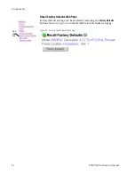
Страница 36: ...uration Recall Factory Defaults Web Page Factory default settings can be recalled by selecting the Factory Defaults button shown in Figure 20 on the Recall Factory Defaults web page Figure 20 Factory Default Recall Web Page Use this link ...

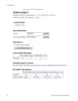
Страница 37: ... When the Restore upon Install box has been checked the current configu ration saved to this slot is saved as slot memory When the current module is removed and another module of the same type is installed the configuration saved to the 8900NET module will be downloaded to the new module The box must be checked before the current module with the saved configuration is removed Frame Heath Reporting...

Страница 38: ...38 8960ENC Instruction Manual Configuration Figure 21 8960ENC Slot Config Web Page ...

Страница 39: ...the software update for complete details Currently the only recommended method of software updating is done with a software kit 8900 FLOAD CBL that includes a CD ROM with the current software files and a serial cable assembly available from Grass Valley Refer to the 8900 FLOAD CBL Software Upgrade Instruction Manual in pdf format on the CD ROM for complete updating instructions and the required so...

Страница 40: ...e Analog Outputs Number of outputs 4 Signal type Composite analog video conforming SMPTE170M for NTSC and CCIR624 for PAL B Signal level 1 V peak to peak nominal 6 dB Clamping level 0 0 VDC 20 mV 0 0 mV Output impedance 75 Ω Connector type 75 Ω BNC on 8900 frame Output return loss 40 dB to 5 5 MHz Output isolation 46 dB to 5 5 MHz Frequency response 0 1 dB to 5 5 MHz Differential phase 0 5 degrees...

Страница 41: ...300 mV p p 3 dB Input impedance 75 Ω or high impedance jumper selectable Connector type 75 Ω BNC on 8900 frame Return loss 36 dB to 5 MHz RMS signal to noise 40 dB to 5 MHz SCH error 60 degrees Color frame locking Composite analog video output and reference signal must be within 10 video lines phase difference or color frame lock will be in free run mode Environmental Frame temperature range See G...

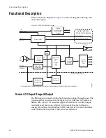
Страница 42: ... pro cessing Error Detection Handling EDH is tested by the microcontroller which flashes the Fault LED when errors are detected 12V Module Slot ID Fault Reporting Local User Interface Intra frame Control Interface 4 2 2 SDI Input 10 10 10 4X NTSC PAL 2X SDI Optional Submodule Available with Frame Communication Upgrade The main encoder module automatically recognizes the attachment of the frame syn...

Страница 43: ... is locked to the selected reference in the horizontal and vertical domain in 37 ns steps 10 bit Encoder and Output Driver The 10 bit precision encoder can be switched through auto manual stan dard selection to multi standard outputs NTSC PAL B PAL M Fine phase adjustment is available within a 0 45 ns range The oversampling restoration filter gives an exceptionally flat response and a linear phase...

Страница 44: ...itch combination interface with a preset option of the factory recall settings All the functions are remote read writable through the intraframe control interface available in 8900TX TF TFN frames The Fault Reporting output is pulsed in case of loss of input signal Regulator The input 12 V is stepped down to 5 V and 5 V using an on board switched mode drop buck regulator The regulator does not sta...

Страница 45: ...y of input signals Verify that source equipment is operating correctly Check cable connections Refer to Figure 5 for the location of PWR LED and Table 2 on page 13 for proper LED indications If the module is still not operating correctly replace it with a known good spare and return the faulty module to a designated Grass Valley repair depot Call your Grass Valley representative for depot location...

Страница 46: ...nternal faults and normal operation Pass Signal input states including valid present pass not present or invalid warning not monitored and not available no signal inputs Reference input states including locked valid pass not locked invalid warning and not monitored Signal output states with reporting functionality reference output LEDs LEDs on modules in the frame and on the front of the 8900TF TF...

Страница 47: ...etwork Interface Instruction Manual Web Browser Interface When the 8900NET module is installed in the frame a web browser GUI can indicate frame and module status on the following web pages Frame Status web page reports overall frame and module status in graphical and text formats Module Status web page shows specific input and reference signal status to the module along with enabled options and m...

Страница 48: ...d on the 8900NET module enabled status reports are sent to an SNMP Manager such as the Grass Valley s NetCentral application There are both hardware and software report enable switches for each report Both must be enabled for the report to be sent Software report switches are set on the 8900NET Configuration web page for the Frame the 8900NET module and each module slot Refer to the 8900NET Networ...

Страница 49: ...l control 20 remote control 35 summary table 17 C calibrated levels 30 chroma level local control 20 remote control 30 summary table 16 chrominance signal local control 20 remote control 35 summary table 17 configuration 18 local 18 Newton Control Panel 16 Remote GUI 22 summary 15 summary table 16 connectors 11 control panel 22 controller module 8 cross color removal local control 21 remote contro...

Страница 50: ... Frame Sync option 10 L Learn Module Config button 37 line 21 setup local control 20 summary table 16 line 22 setup local control 20 summary table 16 locate module 37 lock source 32 lock source selection local control 21 remote control 32 summary table 16 loop through 11 luma level local control 20 remote control 30 summary table 16 M manual freeze 32 manual standard selection local control 20 rem...

Страница 51: ...ware updating 39 standard recognition local control 20 remote control 27 summary table 16 Standard Selection web page 27 status monitoring 46 Status web page 26 submodule 18 switches 18 sync timing adjustment 32 T termination 11 test mode enable local control 21 remote controls 35 summary table 17 test signal selection local mode 21 remote control 35 summary table 17 timing 32 Timing web page 32 t...

Страница 52: ...52 8960ENC Instruction Manual Index documentation 2 FAQ database 2 Grass Valley 2 software download 2 ...

Отзывы: