


15
•
The tree cuttings should be preceded with preparation of the
work place consisting of the removal of lower interfering branches
and clearing the area around the tree trunk.
•
Do not work in strong wind, which may influence the predicted
tree falling direction and cause its uncontrolled felling.
•
Do not carry out cuttings in conditions of limited visibility, when it
is foggy, rains or snows.
•
Do not overreach and do not cut above your shoulder height, or
when standing on a tree, ladder, scaffold, trunk, etc.
•
A
well-equipped first aid kit should be available near the work
place.
To prevent saw recoil follow below instructions:
•
N
ever start or guide a cut with the tip of the guide bar!
•
A
lways start cutting with saw previously switched on!
•
Ensure the cutting chain is sharp.
•
N
ever cut more than one branch at a time. When cutting off, watch
out for surrounding branches. When cutting a tree through, watch
out for nearby tree trunks.
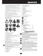
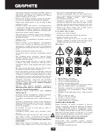
Explanation of used symbols
1.
Caution, use precaution measures
2.
Fire hazard
3.
Exhaust gas poisoning hazard
4.
Use protective gloves
5.
Switch off the engine and remove wire from the ignition plug
before commencing any maintenance or repair
6.
Read instruction manual, observe warnings and safety
conditions therein!
7.
Use head, eyes and ears protection
8.
Danger of recoil
9.
Use protective clothes
10.
Use protective shoes
11.
Do not put your hands or legs close to cutting parts
CONSTRUCTION AND USE
Petrol chain saw is a hand-held tool.
I
t is driven by an air cooled, two-
stroke combustion engine. Tool of this type is designed for tasks in
home garden. The saw can be used for cutting down trees, cutting
branches, firewood, wood for fireplace and other tasks where cutting
wood is necessary. Petrol chain saw is a tool for amateur use only.
Use the device according to the manufacturer’s instructions only.
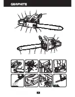
DESCRIPTION OF DRAWING PAGES
Below enumeration refers to the device elements depicted on the
drawing pages of this manual.
1.
Throttle lever lock
2.
Choke cable
3.
Knob for air filter lid
4.
A
ir filter lid
5.
Front handle
6.
Brake lever
7.
Guide bar fixing nuts
8.
Chain tension adjustment screw
9.
Oil feed adjustment screw
10.
Casing
11.
Throttle lever
12.
M
ain handle
13.
Starter line
14.
I
gnition switch
15.
Fuel filler plug
16.
Carburettor adjustment screws, L and H
17.
Low speed adjustment screw T
18.
Oil filler plug
19.
Bumper spike
20.
Guide bar
21.
Chain
22.
Guide bar chain wheel
* Differences may appear between the product and drawing.
MEANING OF SYMBOLS
C
A
UT
I
O
N
W
A
R
NIN
G
A
SSE
M
BLY/SETT
IN
GS
IN
FOR
MA
T
I
O
N
EQUIPMENT AND ACCESSORIES
1.
Guide
bar
guard
-
1
pc
2.
Guide
bar -
1
pc
3.
Cutting
chain
-
1
pc
4.
Bumper spike + bolts
- 1 set
5.
Fuel and oil mix tank
- 1 pc
6.
Sparking plug wrench with screwdriver - 1 pc
7.
Screwdriver
-
1
pc
8.
Hexagonal
key
-
2
pcs
PREPARATION FOR OPERATION
CARRYING THE CHAIN SAW
Prior to carrying the chain saw slide chain cover onto guide bar
and chain. When carrying the chain saw, hold it by front handle.
Do not carry the saw when holding main handle. If several
cuttings are to be made, switch off the chain saw with the ignition
switch between consecutive tasks.
INSTALLING THE BUMPER SPIKE
The bumper spike should be attached to the chain saw at all times
due to safety reasons. The bumper spike is a support point and
reduces the kickback risk.
•
Fasten the bumper spike (
19
) to the chain saw case using bolts
(included).
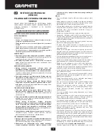
INSTALLATION OF GUIDE BAR AND SAW CHAIN
Prior to guide bar installation remove plastic transport spacer,
placed on guide fixing screws under the guard. Use pin and
adjustment screw for adjustment of chain tension. It is very
important that the bolt located on adjustment screw falls into
hole in the guide bar during installation of the guide bar.
You can move the bolt to the front and back by turning the
adjustment screw. Those parts must be set appropriately prior to
starting guide bar installation in the saw.
Guide bar and chain are supplied separately.
•
Brake lever (
6
) must be in the upper (vertical) position (
fig. A
).
•
Unscrew the guide bar fixing nuts (
7
) and remove the casing (
10
).
•
Put the chain (
21
) onto driving chain wheel located behind the
clutch.
Содержание 58G943
Страница 2: ...2...
Страница 28: ...28 90 1 2 3 4 5 6 7 8 9 10 11 1...
Страница 31: ...31 6 12 5 12 35 5 H 6 7 21 20 8 3 4 I 7 J 1 11 K 11 L...
Страница 32: ...32 450 M 1 3 N 2 5 M 19 O 12 19 12 1 3 1 3 P R S 5 4 3 4 d T 4...
Страница 35: ...35 90 1 2 3 4 5 6 7 8 9...
Страница 39: ...39 L 450 M N 2 5 M 19 O 12 19 12 1 3 P R...
Страница 40: ...40 S 5 4 3 4 d T 4 4 5 14 7 10 20 21 e 20 U 22 f W 21 15 g X 15 18 h Y 18...
Страница 93: ...93 a b a b c a b c d a b 90...
Страница 97: ...97 7 21 20 8 3 4 I 7 J 1 11 K 11 rys L 450...
Страница 98: ...98 M N 2 5 M 19 O 12 19 12 1 3 P i R S...
Страница 114: ...114 1 2 3 4 5 6 7 8 9 10 11 1 2 3 4 5 6 7 8 9 10 11 12 13...
Страница 117: ...117 1 2 6 6 12 5 12 35 5 H 6 7 21 20 8 3 4 I 7 J 1 11 K 11 L...
Страница 118: ...118 45 M 1 3 N 2 5 M 19 O 12 19 12 1 3 1 3 P R S...
Страница 134: ...134...
Страница 135: ...135...
Страница 136: ......


