


Page 48
Section 9: Commissioning
Flow rate = Heat output (kW) ÷ Temperature differential (K)
÷ Specific heat capacity of water (4.2kJ/kgK) *
Example:
Heat output = 12kW
Differential = 5K
Specific heat capacity of water = 4.2 kJ/KgK
Flow rate = 12 ÷ 5 ÷ 4.2 = 0.571 kg/sec
= 0.571 x 60 = 34.3 kg/min (or 34.3 litres/min)
! NOTE !
* The use of an antifreeze/inhibitor/biocide fluid will alter
the value of Specific Heat Capacity but, as the difference is
minimal, use 4.2kJ/kgK as a constant for the calculation of
flow rate.
This flow rate can be calculated as follows:
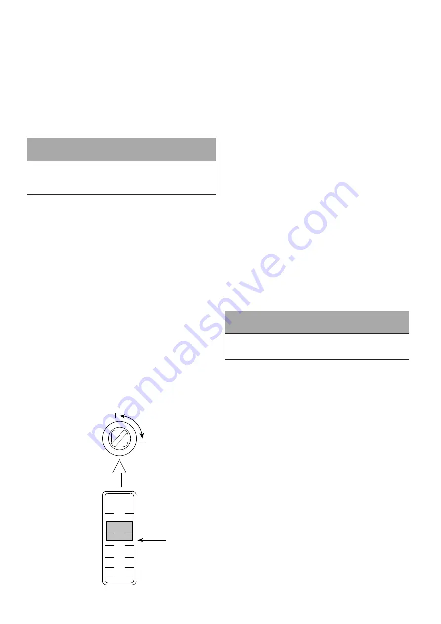
Figure 9-3:
Flow regulator adjustment
To set the flowrate, the system should be set to maximum demand,
i.e. with all emitters and zone valves open. The flow rate is then
adjusted by rotating the regulating valve until the required flow rate
is indicated on the flow regulator scale.
•
To increase the flow rate - rotate valve anticlockwise
•
To decrease the flow rate - rotate valve clockwise
The actual flowrate must be read from the LOWER edge of the
float, in the flow regulator window. Refer to Figure 9-3.
Grant Aerona³ heat pumps are supplied with the circulating pumps
set to the highest of three possible performance curves. In order to
achieve the required flow rate it may be necessary to select one of
the other pump performance curves. Refer to Section 8.3.6.
If two heat pumps of the SAME output are connected to a Grant
Combined Volumiser/Low Loss Header, both flow regulators should
be set to the SAME flowrate, as calculated for the output of each
heat pump.
If the two heat pumps are of DIFFERENT outputs:
a)
Calculate the required flow rate for each heat pump, based on
their respective outputs.
b)
Set the flow rate of each heat pump separately, i.e. with only
one heat pump operating at a time.
Please refer to the installation instructions supplied with the
volumiser/low loss header for further information.
9.14 BALANCING THE PRIMARY CIRCUIT
With the heat pump installed as described in these installation
instructions, any hot water cylinders connected to the system filled
with water and the primary circuit filled and vented (refer to Section
4.2); the primary circuit can be balanced.
To balance the primary circuit:
1. Access the automatic system bypass valve (see Figure 4-1).
2.
Fully open all TRVs fitted to radiators on the system.
•
In warmer climates it may be necessary to slacken
the TRV heads off, in order to prevent the ambient
temperature closing the TRVs down.
3. Ensure the automatic bypass valve is fully closed.
4.
Set any circulating pumps fitted to the system to their optimum
setting.
•
Initially set the circulating pump contained in the Aerona³
heat pump to level 1 (minimum). Refer to Section 8.3.6.
•
If the system requires, increase the pump speed to level
2 or even level 3.
5. Turn the heat pump on, operate the system in space heating
mode and allow the system to start heating up.
6.
With the system flow temperature approaching its set value,
check the temperature difference between the flow and return
pipes connected to each heat emitter on the system, starting
with the emitter closest to the heat pump.
•
In the case of a Grant Aerona³ heat pump, this
temperature difference should be approximately 6 to 8°C.
7.
In instances where this temperature difference is too low,
close the appropriate radiator lockshield valve fully and open
no more than half a turn. Repeat this process for the next
radiator in the circuit until the desired flow/return temperature
difference has been achieved for all heat emitters on the
system.
! NOTE !
Throughout the process of balancing the system, it is
important to ensure that the heat pump is continuously
operating to provide heat to the space heating circuit.
8.
Turn the heat pump off and allow the system to cool.
9. While the system is cooling and with the automatic bypass
valve still fully closed, tighten any TRV heads that were
slackened and fully close all TRVs on the system.
10. With all TRVs on the system fully closed, turn the heat pump
on and operate the system in space heating mode. Allow the
system to reach operating temperature.
11. Open the automatic bypass valve until you detect that water is
just starting to flow through it. The valve is opened by rotating
it anti-clockwise (viewed from beneath valve).
12.
Ensure the heat pump is operating at the chosen flow
temperature without modulating down.
If the appliance is modulating down, open the automatic
bypass valve slightly until a situation is achieved where all
TRVs on the system are fully closed and the heat pump
continues to run at the chosen operating temperature.
13. Leave the automatic bypass valve in this position, open all
TRVs fully and allow the system to run according to the
householder’s requirements.
The primary circuit has now been balanced and the automatic
bypass valve has been set.
Scale: X : X
Paper Size: A4
Revision Details:
1.0 25/04/22 Drawing approved.
Project Title: Flow regulator adjustment
Status: Approved
Rev Date: 25/04/22 Drawn By: CG
Checked By: PS
Revision: 1.0
This drawing and its content is subject to copyright. Use other than for its original intended purpose must be arranged with an employee of
Grant UK Ltd.
Hopton House, Hopton Industrial Estate, Devizes, Wiltshire, SN10 2EU, tel; 01380 736920
L/min
42
35
28
20
12
5
30 L/min
Содержание Aerona 3 HPID10R32
Страница 5: ...Page 5 Page intentionally left blank ...
Страница 97: ...Page 97 Notes Notes ...
Страница 98: ...Notes Page 98 Notes ...
Страница 99: ...Page 99 Notes Notes ...