background image

PREPARE A FOUNDATION FOR YOUR 

GRANDIO GREENHOUSE

3

8X8 GRANDIO ELITE BARN STYLE 

GREENHOUSE DIMENSIONS


ROOF PEAK HEIGHT 

1


3

/

4


GUTTERS 

61”

EAVE HEIGHT

DOOR  HEIGHT

97 3/8”

44”

8X8

LEFT SIDE

97 3/8”

74”

95 5/16”

BASE 3


1

/

4


Before assembling your new greenhouse, a proper 

foundation must be prepared. A number of anchor-

ing options are acceptable, based on wind and 

ground conditions in your area.

Pre-read pages 6-9 for base kit assembly information.  

Go to www.grandiogreenhouses.com for founda-

tion ideas and tour our online learning center for 

tips, tricks and videos for putting your greenhouse 

together.


Transparent Film

Opal White Film

Polycarbonate 

Panels

Sun

The UV-Protected side is covered with transparent film 

and must face toward the sun. The side covered in white 

film will always face the interior of the greenhouse.  We 

suggest you peel all film off completely prior to assem-

bly and use a permanent marker to place a small “X” on 

the lower right corner of each panel on the transparent 

side that faces the sun, each panel has a sticker labeling 

the panel number and this side always faces the sun or 

outward as well. DO NOT REMOVE LABELS UNTIL 

YOU INSTALL PANELS. The “X” is suggested in case 

you dis-assemble your greenhouse in the future so you 

may identify which side has the UV coating. Always use 

gloves when handling the polycarbonate panels as the 

edges can be very sharp.  

IMPORTANT: POLYCARBONATE PANELS

Содержание ELITE

Страница 1: ...SERMANUAL 2013 Grandio Greenhouses Backyard Living Source Inc All rights reserved 2015 Manual Edition Extendable Greenhouses Grandio Elite 8x8 Shown In Image 2015 GRANDIO ELITE 8x8 KIT MANUAL INCLUDES INSTRUCTIONS FOR BACK DOOR TRANSFORMATION ...

Страница 2: ...Contact your insurance company to make sure your Grandio Greenhouse will be covered on your policy Call your local utilities companies before digging Do not attempt to begin construction on a windy day Your greenhouse should be built on a flat level surface allowing for drainage Read this entire manual to get familiar with all pieces and parts prior to beginning assembly Follow the steps outlined i...

Страница 3: ...s inside The clear side has a UV coating and we recommend marking a small x on a corner of each panel to determine which side has the UV Coating as you cannot visually determine with your eye in the case of future disassembly Due to shipping the grooves of some of the aluminum profiles may be too small to insert into the polycarbonate sheet you may carefully use a screwdriver to pry the framework ...

Страница 4: ...rent Film Opal White Film Polycarbonate Panels Sun The UV Protected side is covered with transparent film and must face toward the sun The side covered in white film will always face the interior of the greenhouse We suggest you peel all film off completely prior to assem bly and use a permanent marker to place a small X on the lower right corner of each panel on the transparent side that faces th...

Страница 5: ...L08A X L08C X L08C X 609 609 610 630 609 609 610 630 L08A 622 L 622 R 603C 603C L08C X 603C 616 618 603C 616 618 L08C X 623B 623B 623B 623B 606 WS 606 WS Y7 Y7 Y7 Y7 Y7 Y7 Y7 Y7 Y8 Y8 Y8 Y11 Y9 Y10 Y10 Y9 Y8 Y8 Y8 Y11 Y11 Y11 Y11 Y11 Y11 Y11 Y3 1 Y3 2 Y2 2 Y2 1 Y6 Y6 Y6 Y6 Y1 Y1 Y1 Y1 Y1 Y1 Y4 1 Y4 2 Y5 1 Y5 2 Outside View DIAGRAM SHOWS THE ASSEMBLED 8 x8 BASIC CONFIGURATION GRA ELI 8A GRA ELI 8P ...

Страница 6: ...U S E S GRANDIO Introduction 1 Safety Instructions 2 Prepare For Assembly 3 Diagram of Assembled Grandio Elite 8x8 4 Base Kit Assembly Information 6 Base Kit Parts Lists 7 Base Kit Assembly and Installation 8 9 Front Wall Assembly 10 15 Back Wall Assembly 16 21 Middle Assembly 22 37 Door Assembly 38 43 Interior Roof Supports 44 GRA ELI 8A Parts List 45 47 GRA ELI 8P Parts List 48 GRA ELI BD Parts ...

Страница 7: ...Wind Conditions If you live in a windy location there is no way to build a 100 storm safe greenhouse but there are a number of things you can do to minimize the chance of damage Ensure that the base is level and square be sure all panels are tightly in place and that all aluminum extrusions are tight The main problem is usually that wind gets into the greenhouse and the pressure pushes a panel out...

Страница 8: ...4 BA S1 BA S2 BA S1 BA S2 BA C3 BA C3 BA C3 BA C3 1 1 Layout all base kit pieces to prepare for assembly Note that one BA S1 will be at the front and one BA S1 will be at the back and the BA S2 s will be on the sides See diagram BA S03 BA M03 W05 BA A1 M6 14 NUT CLIP 9 13 16 in 250 mm GRAPHIC PART NAME SIZE LOCATION QUANTITY 28 28 9 4 7 STEP ONE ...

Страница 9: ...oles and push together to an even and tight position and use the BA S03 bolt and BA M03 collard nut combo tighten the collard nut on the inside of the base kit using the 10mm wrench Repeat this process on all corners See and Note Placement of BA S1 will be at front and the back while the BA S2 s will be the sides of your greenhouse base 1 3 For ground installation only insert the 4 BA A1 s and 4 B...

Страница 10: ...UST BE LEVEL SQUARE FOUNDATION MUST BE PROPERLY ANCHORED PRIOR TO GREENHOUSE ASSEMBLY B Holes are present in base kit for anchoring bolts You determine and aquire proper fastener prior to installation Discard the BA A1 for deck installations OR Use Quikrete fast setting concrete to anchor base Pour in Quikrete and water no mixing required Not Included DECK OR PATIO INSTALLATION BA S1 BA C3 BA S2 B...

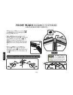
Страница 11: ...A FL 601B 601B 619 L08D 603C 603E 604 R Y3 1 Y3 2 Y1 Y1 Y2 2 Y2 1 L08A X L08A X GRANDIO T I P BOLT INSTALLATION TIP Locate all nuts and bolts pre thread and place in the groove of the extrusion to make installation easier Move up or down for exact placement 606 WS 606 WS Inside View This picture shows the inside view of front section fully assembled All parts for front assembly will be found in bo...

Страница 12: ...stall WG02 s into 2 601B s then tighten S05 screws when extrusions are completely tight see Note the fat end of the WG02 will always be on the bottom side see GRANDIO T I P PRETHREAD SCREWS TIP Locate all WG01 WG02 and S05 screws pre thread these to make installation easier Note that the fat end on the WG02 will always face downward Inside View 601B 601B 601B 601B 603E WG01 WG02 WG02 WG01 601B 601...

Страница 13: ...els Sun The UV Protected side is covered with transparent film and must face toward the sun The side covered in white film will always face the interior of the greenhouse We suggest you peel all film off completely prior to assem bly and use a permanent marker to place a small X on the lower right corner of each panel on the transparent side that faces the sun each panel has a sticker labeling the...

Страница 14: ...ese holes should face the ground during assembly S04 ML01 604 R 619 INSIDE DOOR FRAME TIP If necessary you may use a screwdriver to wedge behind the bolt head This prevents bolt from falling into the track S04 601A FR ML01 619 INSIDE Inside View GRANDIO T I P Note the larger holes on 601A FR and 601A FL front pieces need to face the top front of the greenhouse GRANDIO T I P BOLT INSTALLATION TIP L...

Страница 15: ...he 606 WS to allow room for panels to fit 2 9 Insert Y1 polycarbonate panels into place make sure Y1 s slide completely into 606 WS as shown in 2 10 Set 2 603C s atop the Y1 panels then attach 2 L08D s to the 603C s 601A s and 604 s using S04 ML01 fasteners make sure it is snug with the tops of the Y1 panels then tighten fasteners See 2 11 Insert the Y2 2 and Y2 1 polycarbonate panels as shown in ...

Страница 16: ... frame with carpenter square or use a measuring tape to make sure corner measurements are the same also check distance across from the top of 601A s and also to the bottom of the 601A s across make sure distance is the same Tighten L08A X s to hold squareness as shown in 15 STEP TWO 603C L08D 604 L 601A FL 601A FR 619 L08D 603C 604 R Y1 Y1 Y2 2 Y2 1 Y3 1 Y3 2 601B 601B Inside View W04 2 W04 2 WG02...

Страница 17: ...panels in the sun or near plants until fully assembled GRANDIO T I P Transparent Film Outside Greenhouse Opal White Film Inside Greenhouse Polycarbonate Panel Sun WG01 L08B 603C 603C 602C 602D 602D 603C 603C 601A 601A L08B X L08B X L08A 601B 601B 601B 601B 601B WG02 WG02 606 WS Y1 Y1 Y1 Y1 Y4 1 Y5 1 Y5 2 Y4 2 WG02 WG02 606 WS This image shows the inside view of the back wall assembly All parts for...

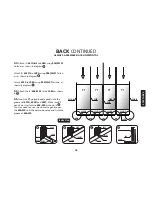
Страница 18: ...between the extru sions tighten the S05 screws see Inside View 601B 601B 601B 601B WG01 WG02 WG02 GRANDIO T I P PRETHREAD SCREWS TIP Locate all WG01 WG02 and S05 screws loosely pre thread these to make installation easier Note that the fat end on the WG02 will always face down WG01 601B 601B S05 WG02 WG02 WG01 FAT END FAT END BACK CONTINUED ALWAYS ASSEMBLE BACK HORIZONTAL IMPORTANT Be careful movi...

Страница 19: ...6 WS s to the L08A as shown in 3 6 Insert the Y1 polycarbonate panels into the grooves of 601A 602D and 602C Make sure Y1 panels are inserted into 606 WS as shown in You may need to use a screwdriver to gently open the 606 WS to fit the polycarbonate panels into the groove of 606 WS ML01 601A L08A S04 INSIDE 602D L08A INSIDE ML01 S04 602C L08A Polycarbonate Panel 606 L08A Inside View 18 STEP THREE...

Страница 20: ...to each 601A B 602D and the 602C When aligned tighten the middle first and work your way outward See diagrams 3 8 Insert the Y5 1 and Y5 2 polycarbonate panels into place Then insert the Y4 1 and Y4 2 into place as shown in the diagram 603C L08B 602D S04 ML01 L08B 601A B Inside View L08B 603C 603C 603C 603C 603C 603C L08B 602C 603C 602D L08B BACK CONTINUED ALWAYS ASSEMBLE BACK HORIZONTAL ...

Страница 21: ...02C When all members are snug tighten all fasteners to lock into place Y1 Y1 Y1 Y1 601A B 601A B 602C 602D 602D Y4 1 Y5 1 Y5 2 Y4 2 601B 601B 601B 601B 601B W04 2 W04 2 WG02 WG02 WG01 601B 601A WG02 GRANDIO T I P BOLT INSTALLATION TIP Locate all nuts and bolts pre thread and place in the groove of the extrusion to make installation easier Move up or down for exact placement BACK CONTINUED ALWAYS A...

Страница 22: ... as shown in GRANDIO T I P Square by loosening bolts attached to the tops of the L08B X use measuring tape to make sure corners to corner measures the same ML01 S04 602D L08B X L08A 21 STEP THREE Inside View 602C 602D 602D 601A B 601A B L08B X L08B X 601A B S04 ML01 L08B X L08A BACK CONTINUED ALWAYS ASSEMBLE BACK HORIZONTAL ...

Страница 23: ... to complete the middle assembly of your greenhouse The more people the merrier at this stage of assembly Warning The person s holding the front or back sections vertical must continue to do so until the L08C X angle supports are attached securely to the front and base as shown in step 4 5 Failure to hold front vertical will cause the front to fall and damage the base kit front framing etc Damage ...

Страница 24: ... in and with the nut and bolt combos 4 4 Attach the front section 619 to the base using 3 S04 ML01 fasteners as shown in then attach the threshold support to the inside of the 619 with 5 self tapping screws included in the package see 2 1 BA S1 604 601A 601A 619 Attaches to the base kit with S04 ML01 Threshold Support will attach with 5 self tapping screws ...

Страница 25: ...olt into the extrusion slide it down to catch the edge of the base kit then slide up and hold up as high as it will go and then tighten the ML01 nut note you will have to switch out the combo that was originally used to the W05 Clip MIDDLE ASSEMBLY CONTINUED BA S1 604 601A 601A 2 BA S2 BA S1 Base BA S1 W05 619 Inside BA S2 601A ML01 S04 Inside View W05 BA S1 ML01 S04 L08A X 619 604 R W05 If you ar...

Страница 26: ...attach the backwall where the 601A s meet the corner of the base as shown in and where 602D s and the 602C meet the BA S1B see Then use W05 Clip combos to attach the corner 601A s to the base kit as shown in you will have to switch out the combo that was originally used to the W05 Clip 601A 601B L08B X L08C X L08B W05 Base 602C 602D Outside Inside L08C X L08C X 602D 602D 602C BA S2 or BA S6 601A M...

Страница 27: ...e attach the ridge to front and back by sliding into place as shown in and using S04 ML01 fasteners attach the 607 to the 601B s as shown in 607 607 601B Side Angle View Outside View 607 601B 601B 26 STEP FOUR 607 601B 601B Inside View S04 ML01 ...

Страница 28: ...w move the loosened S04 ML01 nut and bolt currently attached to the 601A upward to firmly secure the L08C X 609 and 601A together as shown in 3 Repeat steps 1 and 2 for the other end of 609 4 With one side firmly secured move to the other side and repeat steps 1 2 and 3 MIDDLE ASSEMBLY CONTINUED GRANDIO T I P Remove only one L08C X at a time If all L08C X s are removed the structure will collapse ...

Страница 29: ...09 Profile View Groove 602A Note the line on the 609 that shows the exact placement of the 602B s and the 602A s when installed correctly Inside View 609 ML01 S04 601B 601B FRONT 601B 609 601A 1 2 4 11 Note orientation of the 609 see 1 Attach the mid roof 609 s with S04 ML01 nut and bolt on both sides see MIDDLE ASSEMBLY CONTINUED 28 STEP FOUR ...

Страница 30: ...eference 2 Hold the 602A in place and attach the top of the 602A to the 609 using S04 ML01 nut and bolt As shown in 3 Repeat steps 1 and 2 on all four corners where the L08C X s meet the base kit 4 Now attach the bottom of 602A to the Base using a S04 ML01 nut and bolt as shown in and to the 609 with an S04 ML01 combo as is shown in Inside View 609 602A Inside View 601B L08C X 602A L08C X BA S2 60...

Страница 31: ...ides loosen bolts attached to L08C X in all upper corners Using a level adjust 602A and tighten bolts Repeat in every corner until the greenhouse is plumb The top edges of Y7 s will align when greenhouse is level or plumb GRANDIO T I P Transparent Film Outside Greenhouse Opal White Film Inside Greenhouse Polycarbonate Panel Sun 601A L08C 606 WS MIDDLE ASSEMBLY CONTINUED ...

Страница 32: ...he exact placement on the outside see Attach 1 602B between the 2 609 s in the middle only on both sides of roof Do not attach remaining 602B s to lower roof section until roof vents are attached see 609 602A Inside View ML01 S04 602B 602B 609 607 EXACT PLACEMENT Outside View 609 602B ML01 S04 602B Inside View MIDDLE ASSEMBLY CONTINUED ...

Страница 33: ...See and Note that you may need to loosen the bottoms of some of the 602B s to slide the 630 into place as the fit is very tight Check that all nut and bolt combos are tightened again after installation of 630 32 STEP FOUR MIDDLE ASSEMBLY CONTINUED Left Profile View Right Profile View The two profiles should be flush at ends when installed correctly The two profiles should be flush at ends when ins...

Страница 34: ...ee Window positions are your discretion however must be in the middle for support do not place nearest the front or back as you will need a 602B support to keep in window vent in place Place directly across from each other for best cross draft ventilation see for optional placement GRANDIO T I P Place roof windows in desired location before attaching all 602B s Y10 Y10 Y10 Y10 618 Z02 Z02 Z02 Z02 ...

Страница 35: ... shown in the image and MIDDLE ASSEMBLY CONTINUED Y10 Y10 602B 602B Outside View 602B 609 607 EXACT PLACEMENT 602A 602A 602A 602A 34 STEP FOUR UP 602B 609 Profile View Groove 602A Note the line on the 609 that shows the exact placement of the 602B s and the 602A s when installed correctly ...

Страница 36: ... the first two holes of the handle to the second and third pins of HQC02 Then attach HQC02 into 603C s track with S04 ML01 nuts and bolts see 603C 618 616 616 603C 616 HQC01 Z04 HQC02 Y10 HQC01 Y10 Y10 603C Inside view of 603C 603C 602B W04 Note If you are installing automatic roof vent openers follow those directions for correct installation SAVE MANUAL OPENERS FOR WINTER SWITCHOUT HQC01 603C HQC...

Страница 37: ...utters are in place You may want to place a piece of tape on the panel to prevent sliding as shown below once the panels are in place 4 20 Slide 610 into 609 s groove as shown in diagram Repeat on both sides Remove tape after gutter is fully installed Y9 Y8 Y8 Y8 609 MIDDLE ASSEMBLY INSTRUCTIONS CONTINUED The two profiles should be flush at ends when installed correctly ...

Страница 38: ... as shown below Squeeze a small amount of rubberized silicone into the ends of ridge mid roof and gutters to secure pressure fit end caps As shown in images to the right Use Z03 screws to attach the JG03A and JG03B endcaps along with the silicone adhesive MIDDLE ASSEMBLY INSTRUCTIONS CONTINUED The two profiles should be flush at ends when installed correctly ...

Страница 39: ... Bottom View Inside View DOOR ASSEMBLY DIAGRAM This image shows the inside view of Right Door Assembly All parts for door assembly will be found in box GRA ELI 8A and GRA ELI 8P Use the 2 head Phillips Screw Driver for installation If you are using the Back Door Transformation kit you will repeat steps 5 1 5 11 to install the Back Door these parts will be found in box GRA ELI BD ...

Страница 40: ...rom assembling the wrong way Be careful not to strip the phillips heads when assembling 5 1 Insert J08A into the bottom of the 622 note the bottom groove is smaller than the top groove of 622 see 5 2 Use the Z01 screws to attach the 622 to the 623B 623A and 620 as shown in 5 3 Insert Y6 windows into position as shown in 623B Z01 620 Z01 Z01 623B 623A 622 620 623A 622 620 Y6 Y6 GRANDIO T I P Transp...

Страница 41: ... 5 6 Follow the same instructions for the other door making sure that the 622 L and 622 R with the double ball catch match up so doors will latch closed and slide properly Y6 Y6 623B 623A 620 622 R Double Ball Catch Z01 Z01 Z01 622 Side View Of Top Double Ball Catch on the 622 R 622 R UP UP Side View Of Bottom Note the orientation of the 622 L and 622 R Also make sure the right side is facing out ...

Страница 42: ...with the holes on the 603D door header With one person inside the greenhouse line up hanging door track L21 with door header 603D move bolts on L21 to line up with bolt holes on door header 603D From the inside hand tighten the ML01 nut while the person outside is holding the L21 in position you will now center on the front of the greenhouse and tighten the S02 ML01 combo ...

Страница 43: ... the 622 HNDL NUT BOLT provided to both doors as shown below in and We included some felt dots in your Grandio Welcome Kit please apply to the inside bottom edge of the 623B as shown in these felt dots will make your doors fit snug and slide smoothly DOOR INSTALLATION Outside View Inside View Top Bottom L21 L21 622 HNDL 622 HNDL NUT BOLT 622 HNDL 622 HNDL NUT BOLT Side Profile View of Hanging Trac...

Страница 44: ...nd L28 to 601A with S02 ML01 as shown below in diagram and Check that the L21 and L28 s are square Attach 2 J07 to the ends of L21 see The L28 should align square to the 601A 5 11 Check that the door locks are snug you may adjust them with screwdriver if needed as they may be tight ened or loosened Top Profile View 601A FR 601A FL Backside View L21 ...

Страница 45: ...roof section where S04 ML01 fasteners are already in place where the 609 and the 602B meet and the 609 and the 601B meet see 6 3 Attach the BZ 1 s to the roof line as shown in diagram with the S04 ML01 The edge of the BZ 1 should meet up to the edge of 609 exactly 6 4 Use CZ 1 s to support the interior wall at the eave using the S04 ML01 See diagram We suggest that you measure down 9 and mark it w...

Страница 46: ...16 in 748 mm 90 1 2 in 2299 mm 83 1 4 in 2115 mm 83 1 4 in 2115 mm 21 7 8 in 555 mm 72 3 16 in 1833 mm 18 1 4 in 463 mm 94 1 4 in 2394 mm 70 3 4 in 1797 mm FRONT RIGHT 70 3 4 in 1797 mm FRONT LEFT 94 1 4 in 2394 mm 21 3 4 in 553 mm 94 1 4 in 2394 mm 94 3 8 in 2397 mm 22 3 4 in 578 mm 22 3 4 in 578 mm 19 11 16 in 500 mm 94 3 8 in 2397 mm 94 1 4 in 2394 mm 94 1 4 in 2394 mm GRA ELI 8A 8x8 GRANDIO EL...

Страница 47: ...CREWS FOR ROOF VENTS Z03 S02 ML01 S04 S05 Z04 S04 ML01 HQC01 HQC02 L28 W11 W13 W16 BZ 1 CZ 1 M3 25 M6 20 M6 14 M6 10 SCREWS FOR WG01 AND WG02 ROOF VENT HARDWARE ROOF VENT ARM ROOF VENT LATCH 19 9 16 in 497 mm SCREW DRIVER MULTI DRIVER 10 MM NUT DRIVER 56 1 2 in 1435 mm 23 5 8 in 600 mm 2 2 2 4 4 4 2 8 5 2 4 13 9 4 6 150 45 4 2 2 2 1 1 1 3 6 GRAPHIC PART NAME SIZE LOCATION QUANTITY GRAPHIC PART NAM...

Страница 48: ...WARE 21 7 16 in 545 mm 95 1 2 in 2425 mm L21 END CAP 69 11 16 in 1770 mm 69 11 16 in 1770 mm 69 11 16 in 1770 mm 21 7 16 in 545 mm 21 7 16 in 545 mm DOORS GRA ELI 8A 8 x8 GRANDIO ELITE ALUMINUM PACKING LIST S10 JG01 JG02 A B JG03 A B GRAPHIC PART NAME SIZE LOCATION QUANTITY 10 2 2 2 2 2 M6 16 ATTACHES 619 TO BASE RIDGE END CAP MID ROOF END CAP GUTTER END CAP ...

Страница 49: ...78 mm 22 3 4 in 578 mm 35 1 2 in 902 mm 35 1 2 in 902 mm 22 3 4 in 578 mm 22 3 4 in 578 mm 22 3 4 in 578 mm 22 3 4 in 578 mm 22 3 4 in 578 mm 22 3 4 in 578 mm 22 3 4 in 578 mm 22 3 4 in 578 mm 22 3 4 in 578 mm 22 3 4 in 578 mm 47 5 16 in 1202 mm 9 1 16 in 230 mm 23 in 585 mm 9 15 16 in 252 mm 19 1 8 in 486 mm 9 1 16 in 230 mm 35 3 16 in 894 mm 35 7 16 in 900 mm 42 13 16 in 1087 mm 34 in 864 mm 57 ...

Страница 50: ...IO ELITE BACKDOOR PACKING LIST 603D 603E 604R 604L L08D 619 622 622R 622L 620 623A 623B L08A X J08A 622 DOOR HANDLES Z01 ML01 S04 ML01 S02 L21 J07 L28 W04 W04 1 W04 2 Y3 1 Y3 2 Y2 1 Y2 2 Y6 GRAPHIC PART NAME SIZE LOCATION QUANTITY 1 1 1 1 2 1 2 1 1 2 2 2 2 4 4 GRAPHIC PART NAME SIZE LOCATION QUANTITY 13 35 4 1 2 2 1 2 2 1 1 1 1 4 M4 30 SCREWS FOR DOORS M6 10 M6 20 95 1 2 in 2425 mm L21 ENDCAP 19 9...

Страница 51: ...d related expenses for removal installation or replacement of the greenhouse or its components are not covered under this warranty 4 This warranty does not cover scratching or scuffing of the product that may result from normal usage In addition defects resulting from intentional damage negligence unreasonable use will void this warranty 5 Liability for incidental or consequential damages is exclu...

Страница 52: ...EUSERMANUAL KEEP IN A SAFE PLACE FOR REFERENCE CONTACT US IF YOU NEED HELP OR HAVE MISSING OR DAMAGED PARTS GRANDIOGREENHOUSES COM BACKYARD LIVING SOURCE INC 9543 W EMERALD ST SUITE 101 BOISE ID 83704 1 866 448 8231 2015ModelGrandioElite8x8 ...

Отзывы: