


14
307–959
SPRAY VALVE REPAIR
WARNING
Always follow the
Pressure Relief Procedure
Warning
on page 8 before doing any repair.
NOTE:
Order repair kit no. 218–960 to repair this spray
valve.
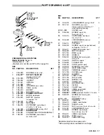
1. Tap out the pin (A). Remove the trigger (B). See Fig
14.
2. Remove the cap (C).Unscrew the fluid housing (D)
Remove the o–ring (J). See Fig 14.
3. Pull the needle (K) out with needle nose pliers.
4. Tap out the seat (G). See Fig 17.
5. Remove the ball (F) and spring (E). See Fig 14.
6. Turn the nylon screw (L) into the packing (H). Insert
the needle (K) through the bottom of the housing (D)
and push the packing out the top of the fluid housing.
See Fig 15.
7. Clean all parts thoroughly. Use a cotton–tipped swab
or pipe cleaner to clean small orifices.
8. Grease the needle (K) and packing (H). Insert the ta-
pered end of the needle into the back (flat) side of the
packing. See Fig 16.
9. Guide the tapered end of the needle into the assem-
bly tool (M) and press the lips of the packing over the
end of the tool. See Fig 16.
10. Grease the free end of the needle (K). Guide the tool
(M) into the fluid housing (D) until the needle pro-
trudes through the bottom of the housing. Lightly tap
the tool end until you “hear” the packing bottom in the
housing. Remove the tool with pliers. See Fig 16.
11. Grease the seat (G) and place it on the fluid housing
so the indentation on the inside diameter faces out.
See Fig 17.
12. Install the spring (E) in the cavity of the valve handle
(N). Install the ball (F) so it is centered on the spring.
See Fig 17.
13. Place the o–ring (J) around the fluid housing. Push
lightly with your fingers to start the threads of the
housing into the valve handle. Torque the housing to
17.5 in–lb (2 N.m). See Fig 14.
14. Push on the needle until you feel some
resistance.
15. Grease the cap (C) and place it on the end of the
needle. See Fig 17.
16. Slide the trigger (B) into place. Install the pin (A) in
the trigger. See Fig 14.
Fig 14
Fig 15
Fig 16
Fig 17
TAPERED END
D
K
H
M
LIPS FACING OUT
OF HOUSING (D)
L
H
D
K
E
F
G
H
N
J
K
D
C
B
A
TORQUE TO
17.5 in–lb
(2 N.m)
C
D
G
F
E
N
SEAT MUST FACE
BALL AS SHOWN


