background image

11

307–959

SPRAYER REPAIR

WARNING

Always follow the 

Pressure Relief Procedure

Warning

 on page 8 before doing any repair.

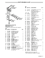
Priming Valve & Tube 

(See Fig 9)

NOTE:

Each new priming valve kit includes a priming

tube and fittings.

1.  Unscrew the nut on the handle (E) of the priming

valve. Unscrew the stem of the handle.

2.  Screw the priming valve (10a) out of the pump hous-

ing (9).

3.  Wrap the threads of the priming valve with

r

 tape as shown in Fig 9. 

Screw  the  valve

snugly into the pump housing. The valve handle

must be parallel with the angled edge of the housing

to avoid interference with the inlet or outlet valves.

4.  Slide the nut (10d) and ferrule (10c) onto the tube

(10e). Install the tube support (10b) in the end of the

tube. Screw the nut onto the priming valve, which will

seat the ferrule.

5.  Completely screw the stem of the handle (E) onto the

priming valve, and then back it out two turns. Screw

the nut hand tight onto the priming valve, then tighten

the stem into the valve.

Suction Tube 

(See Fig 9)

1.  Unscrew the nut (45) from the fluid inlet valve hous-

ing (1). Remove the hose clamp (47). Slit the suction

hose to free the nipple (46).

2.  Insert the nipple (46) through the nut (45). Dampen

the new hose (44) with warm water. Press the hose

over the nipple. Screw the nut onto the inlet valve

housing. Press the hose onto the nipple, leaving

about a 1/8 in. (3  mm) gap between the nut and hose

end.

3.  Install the hose clamp (47) and tighten snugly.

4.  Remove the filter housing (48) and strainer (49) from

the old suction hose and install them on the new

hose. Soften the hose with warm water to 

ease

assembly.

44

45

Fig 9

48
49

10e

10d

10c
10b
10a

9

1

E

WRAP WITH

TAPE

10

46

47

PTFE

PTFE

Содержание WONDER WETTER Jr. 222-684

Страница 1: ...TTER Jr SPRAY SYSTEM 250 psi 17 5 bar MAXIMUM WORKING PRESSURE Model 222 684 Series A 120 Volt AC 1 Phase 1 Amp GRACO INC P O BOX 1441 MINNEAPOLIS MN 55440 1441 COPYRIGHT 1989 GRACO INC This manual contains IMPORTANT INSTRUCTIONS and WARNINGS READ AND RETAIN FOR REFERENCE ...

Страница 2: ...IMUM WORKING PRESSURE Use only compo nents or accessories which are designed for use with the WONDER WETTER Jr spray system Any misuse of this equipment such as modifying parts using incompatible material or solvent or using worn or damaged parts can cause the equipment to rupture and result in serious bodily injury fire explosion and property damage Never alter or modify any part of this equipmen...

Страница 3: ... ceci pourraît entraîner une surpression et un mauvais fonctionnement Vérifier régulièrement toutes les pèces du système et réparez ou remplacez les pièces usées ou abîmées immédiatement ADVERTENCIA Asegurarse de que todos los operadores de este equipo lean entiendan y respeten las precauciones e instrucciones indicadas en este manual PUESTA A TIERRA La puesta a tierra es esencial para reducir el ...

Страница 4: ... and assemble them as shown in Fig 1 following the notes on the drawing 2 Prepare the material according to the manufactur er s recommendations Remove any skin that may have formed on the top of the material If necessary thin the material 3 Plug the power supply cord into a properly grounded 120 V electrical outlet See Fig 2 Do not use an adapter All extension cords must have three wires Use the c...

Страница 5: ...l does not start push the inlet open with a pencil eraser and try priming the system again NOTE Heavy viscosity material may need to be thinned Be sure to follow the material manufac turer s recommendations on thinning 6 When the outlet hose is fully primed the motor runs when there is material demand but appears to shut itself off when there is no material demand NOTE An occasional start and stop...

Страница 6: ...ain the flushing solution Shut off the pump 5 Wash off all external parts of the hoses spray wand spray valve and pump 6 Using clean water flush again Changing water as often as necessary until the system is thoroughly cleaned 7 Finally flush the system with clean mineral spirits for just a few seconds Open the priming valve and turn off the pump Some mineral spirits must be left in the system to ...

Страница 7: ...ee page 8 If it burns out again soon return the system to an authorized repair agency for repair Low or no material flow Clogged spray tip Clean thoroughly after each use Loose inlet hose nut Tighten Worn or damaged priming valve Replace See page 11 Priming valve is open Close Material too thick Thin according to manufacturer s recommendations Damaged pressure switch Replace See page 9 Worn inlet ...

Страница 8: ...ew rectifier so the positive terminal is closest to the fuse holder 65 and then install the screw 33b 4 Connect the power white lead to an unmarked termi nal and the pressure switch lead to the other un marked terminal Connect the black motor lead to the negative terminal and the red motor lead to the positive terminal ON OFF Switch 1 Remove the outlet adapter 2a from the pump hous ing 9 See Fig 6...

Страница 9: ...Slide the retainer 14 over the pressure switch and screw the retainer into the pump housing Torque the retainer to 60 in lb 6 8 N m 6 Guide the pressure switch leads through the base Connect a lead to the power out side of the ON OFF switch 34 and a lead the terminal marked on the rectifier 39 7 Reinstall the front cover To avoid damaging the pressure switch do not drop it and do not press on the ...

Страница 10: ...oughly Use your fingers to press the new guide flat side first evenly into the housing 4 Screw the diaphragm 17 out of the connecting rod assembly 18 5 Use a soft brass or nylon bristle brush to clean the top of the connecting rod and housing Gently clean the bottom of the pump housing 9 avoiding damage to the diaphragm grooves 6 Check the rod motor bearing and eccentric for paint residue If there...

Страница 11: ... nut onto the priming valve which will seat the ferrule 5 Completely screw the stem of the handle E onto the priming valve and then back it out two turns Screw the nut hand tight onto the priming valve then tighten the stem into the valve Suction Tube See Fig 9 1 Unscrew the nut 45 from the fluid inlet valve hous ing 1 Remove the hose clamp 47 Slit the suction hose to free the nipple 46 2 Insert t...

Страница 12: ...of the connecting rod and housing Gently clean the bottom of the pump housing 9 avoiding damage to the diaphragm grooves 7 Install the connecting rod 18 in the connecting rod housing 22 Screw a new diaphragm 17 into the rod just until it touches the bottom T urn the dia phragm 1 4 to 1 2 turn more 6 8 in lb 2 7 3 6 N m Do not turn more than 1 2 turn or the dia phragm will not function properly 8 A...

Страница 13: ...ssemble the parts Check the spin often until you determine the cause of the binding CAUTION 8 Connect the red motor lead to the positive termi nal and the black motor lead to the negative termi nal of the rectifier 39 See Fig 11 9 Reinstall all parts Fig 11 34 37 38 65 33 25 82 81 80 PRESSURE SWITCH 2 LEADS JUMPER WIRE GREEN WIRE MOTOR LEADS WHITE OUT IN RED 39 Motor Brush 1 Remove the bottom cove...

Страница 14: ...f the packing over the end of the tool See Fig 16 10 Grease the free end of the needle K Guide the tool M into the fluid housing D until the needle pro trudes through the bottom of the housing Lightly tap the tool end until you hear the packing bottom in the housing Remove the tool with pliers See Fig 16 11 Grease the seat G and place it on the fluid housing so the indentation on the inside diamet...

Страница 15: ...bber cpld 3 8 npsm m 25 7 6 m 2 85 108 228 NIPPLE 3 8 npt 1 87 108 408 ADAPTER 1 88 220 237 WAND tube 1 89 180 136 ADAPTER tip 1 90 171 602 WASHER tip 1 91 185 559 50_ SPRAY TIP 0 036 orifice 1 92 163 622 FINE FINISH TIP 0 022 orifice 1 93 166 969 WASHER tip 1 Recommended tool box spare parts E F A B D C H G SPRAY VALVE REPAIR KIT 218 960 Includes items A through H Individual parts not sold separa...

Страница 16: ... 65 34a Ref 84 37 38 31 69 30 32 70 18 23 24 20 21 17 11 48 49 52 SEE PARTS DRAWING ON PAGE 17 Part of item 10 see parts drawing on page 17 15 LUBRICATE THREADS TORQUE TO 85 in lb 9 6 N m 16 27 PRESS FIT INTO ITEM 22 22 29 33 LABEL 79 LABEL THIS SIDE 83 LABEL OPPOSITE SIDE 78 52 LABEL 85 36 ...

Страница 17: ...24 108 236 SCREW mach filh No 8 32 x 1 75 4 25 102 313 CAPSCREW hex head 1 4 20 x 1 75 2 26 100 028 LOCKWASHER internal shakeproof 1 4 3 27 108 213 PIN dowel 2 28 108 230 SCREW mach hex washer head self tapping 1 4 14 x 1 2 29 185 511 LABEL designation front 1 30 185 489 MOTOR electric 1 31 181 744 BASE pump 1 32 181 182 HANDLE 1 33 108 224 SCREW thd forming pnh No 8 x 7 8 6 34 105 679 SWITCH togg...

Страница 18: ...KING PRESSURE 219 095 Suction Hose Kit Nylon LARGER DIAMETER OUTLET HOSE Use this hose when using more than 50 ft 15 m of outlet hose for spraying penetrating encapsulants Not in tended for use with lacquer thinners 220 009 Outlet Hose 3 4 ID nitrile cpld 3 8 npsm fbe 50 15 m 250 psi 17 5 bar MAXIMUM WORKING PRESSURE DUAL GUN ADAPTER 220 232 1000 psi 70 bar MAXIMUM WORKING PRESSURE Install on the ...

Страница 19: ...minutes using a 0 036 dia tip or 5 minutes using a 0 022 dia tip Power Supply Cord No 16 AWG 3 wire 6 1 7 m long Wetted Parts Aluminum Brass Viton Delrin Polyurethane Neoprene Tungsten Carbide Stainless Steel Nylon Plated Steel Buna N Polyester Polyvinyl Chloride Weight 13 5 lb 6 1 Kg NOTE Delrin and Viton are registered trademarks of the DuPont Company ...

Страница 20: ...ll be returned to the original pur chaser transportation prepaid If inspection of the equipment does not disclose any defect in material or workmanship repairs will be made at a reasonable charge which charges may include the costs of parts labor and transportation DISCLAIMERS AND LIMITATIONS THE TERMS OF THIS WARRANTY CONSTITUTE PURCHASER S SOLE AND EXCLUSIVE REMEDY AND ARE IN LIEU OF ANY OTHER W...

Отзывы: