background image

333233D

EN

Repair-Parts

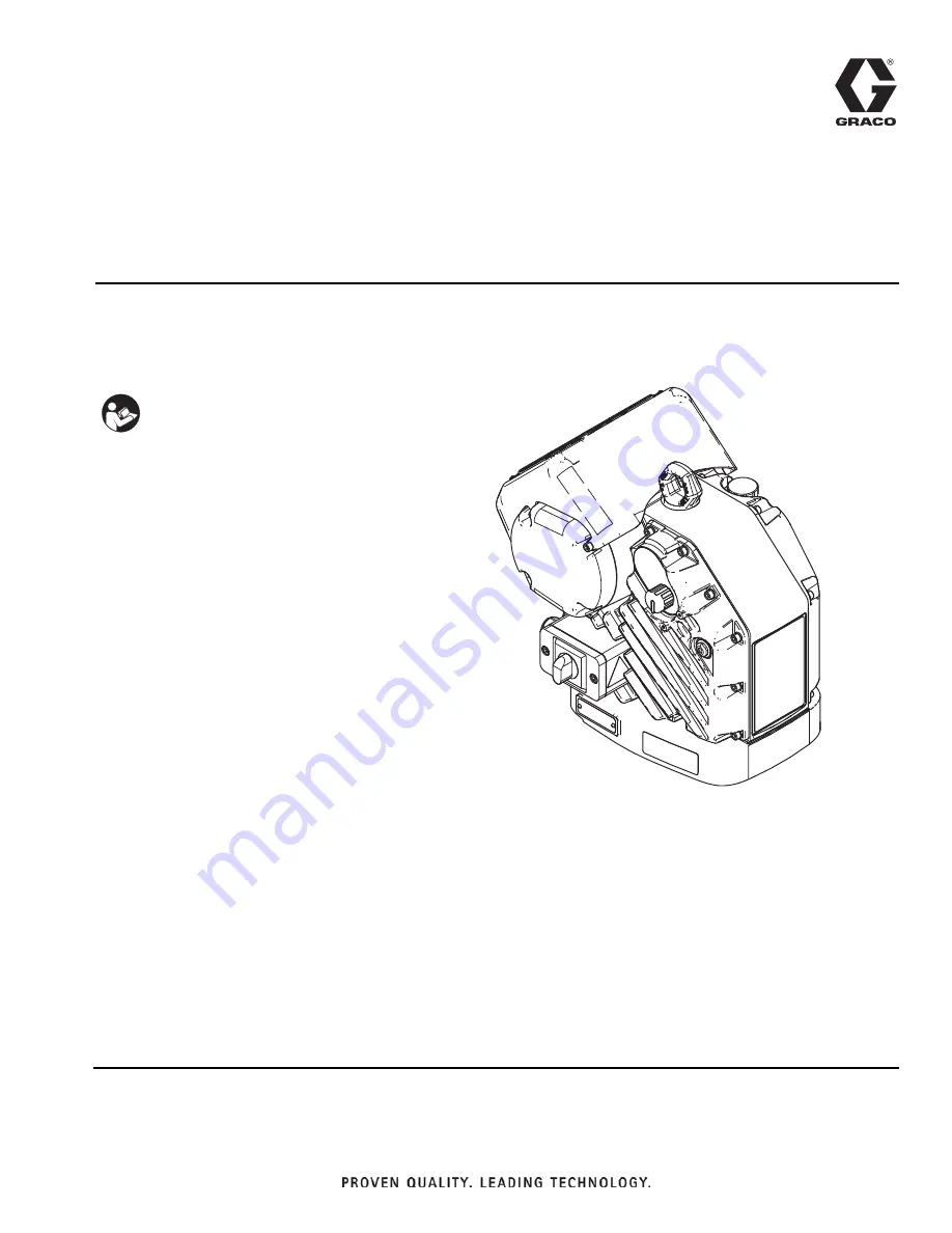
Electric Driver for
High Pressure Airless Sprayer

Electric driver for application of protective coatings. For professional use only.
Not approved for use in explosive atmospheres or hazardous locations.

Model 24V016

Important Safety Instructions

Read all warnings and instructions in this
manual. Save these instructions.

WLD

Содержание 24V016

Страница 1: ...Electric driver for application of protective coatings For professional use only Not approved for use in explosive atmospheres or hazardous locations Model 24V016 Important Safety Instructions Read a...

Страница 2: ...leshooting 9 Power Saving Mode 9 Error Codes 9 Repair 12 Replace Shaft Bearing Assembly 12 Replace Fan Fuses 13 Replace Fan Assembly 13 Replace Electronics Cover 15 Repair Token Cable 18 Software Upda...

Страница 3: ...ring must be done by a qualified electrician and comply with all local codes and regulations FIRE AND EXPLOSION HAZARD Flammable fumes such as solvent and paint fumes in work area can ignite or explod...

Страница 4: ...azards Make sure all equipment is rated and approved for the environment in which you are using it Use equipment only for its intended purpose Call your distributor for information Route hoses and cab...

Страница 5: ...nals See FIG 3 For Series A and B terminals 1L1 and 3L2 For Series C terminals 1L1 and 5L3 NOTE Press gasket against back sealing face of junction box to ease installation of power cord 4 Insert power...

Страница 6: ...cord grip to securely hold power cord in junction box S See FIG 5 Grounding Driver The driver is grounded through the power cord NOTICE If wires get pinched when the screws are tightened damage will o...

Страница 7: ...stment knob H out and turn counterclockwise until it stops Push the knob in to lock 2 Relieve all fluid pressure as explained in your sepa rate sprayer manual Operation The motor will adjust the speed...

Страница 8: ...Fill until the oil level is near the halfway point of the sight glass The oil capacity is approximately 1 0 1 2 quarts 0 9 1 1 liters Do not overfill 4 Reinstall the fill cap Check Oil Level Check th...

Страница 9: ...ause and then the sequence repeats NOTE To clear an error code first try turning the pres sure adjustment knob H counterclockwise until it stops If the status indicator L does not stop blinking shortl...

Страница 10: ...Calibrate the encoder see page 17 Contact your Graco distributor or Tech Service for more information 8 Alarm Encoder Error Cycle power and check the status indicator to see if the error is still act...

Страница 11: ...or Tech Service for more information Driver does not turn over and LED is on Encoder fault Cycle power Contact your Graco distributor or Tech Service for more information Oil is leaking Oil was over...

Страница 12: ...om driver See Change the Oil page 8 5 Reinstall oil drain plug Torque to 18 23 ft lb 25 30 N m 6 Unscrew shaft bearing assembly 14 from driver See Parts page 20 7 Install new shaft bearing assembly To...

Страница 13: ...ect block J and reinstall junction box with two screws and washers NOTE Make sure no wires get pinched during installation Replace Fan Assembly 1 Perform Pressure Relief Procedure page 7 2 Disconnect...

Страница 14: ...junction box S 11 Reattach the ground wire to the grounding screw Tighten ground screw See FIG 11 12 Use a ferrule to connect each fan wire to one of two wires coming out of the motor grommet Then att...

Страница 15: ...2 NOTE Power cord cables excluding the ground wire may remain attached 6 Unscrew ground screws from fan and power cord ground wires 7 Use a wire cutter to cut ferrule tips from fan wires and motor pow...

Страница 16: ...wire E 16 Discard the used cover gasket 53 and the junction box gasket 52 FIG 20 Electronics Cover Removal FIG 21 Tilt Electronics Cover NOTICE All wires must be disconnected before the cover is comp...

Страница 17: ...18 page 15 9 Install gasket 52 junction box sleeve S and tighten four bolts 56 See FIG 19 page 15 10 Install junction box cover G and tighten two screws 6 See FIG 15 page 15 11 Install wires into dis...

Страница 18: ...5 6 times 7 Ensure the auto calibration process is complete before continuing Wait for the LED to stop blinking Repair Token Cable 1 Perform Pressure Relief Procedure page 7 2 Disconnect unit from pow...

Страница 19: ...re code one time Example 1 02 003 would be one blink a pause two blinks as pause then three blinks Normal opera tion will resume after the software version displays 8 Turn off the unit and disconnect...

Страница 20: ...Parts 20 333233D Parts Electric Driver FIG 30 Electric Driver Parts F WL G E D 3...

Страница 21: ...Z25 1 96 127721 KNOB impact control preventer 1 97 127463 SCREW cap socket head 1 101 17B505 SLEEVE junction box 1 102 17B553 ERROR CODE LABEL 1 16Y491 TOKEN CABLE not shown 1 104 16W645 GEAR LUBE 0...

Страница 22: ...D Mounting Hole Pattern FIG 31 Mounting Hole Pattern WL D A B C D 6 186 in 157 mm 6 186 in 157 mm Four 3 8 16 Mounting Holes Six 5 8 11 Tie Rod Holes 8 in 203 mm x 120 bolt circle OR 5 9 in 150 mm x 1...

Страница 23: ...Wiring Diagram 333233D 23 Wiring Diagram FIG 32 Wiring Diagram WL D 5 2 5 7 21 72 72 WL E WL D 1 20 1 1 32 5 21752 2 5 32 5 1 32 5 7 7 7 6HULHV DQG 6HULHV 1 20 1 1 32 5 21752 2 5 32 5 1 32 5 7 7 7...

Страница 24: ...Dimensions 24 333233D Dimensions Driver Dimensions A width 15 30 in 0 390 m B depth 18 3 in 0 465 m C mounted height 18 3 in 0 465 m D total height 21 5 in 0 545 m A A B C D WL D...

Страница 25: ...ous cycle rate To prevent premature pump wear do NOT exceed maximum recommended speed of fluid pump 33 cycles per minute Weight 115 lb 52 kg Operating temperature range 23 to 120 F 5 to 50 C Input vol...

Страница 26: ...material or workmanship repairs will be made at a reasonable charge which charges may include the costs of parts labor and transportation THIS WARRANTY IS EXCLUSIVE AND IS IN LIEU OF ANY OTHER WARRAN...

Отзывы: