


10
Bottom Plate
Extrusion
End Cap B
Bottom Plate
Extrusion
End Cap A
Push on the End Cap
until it snaps into the slot
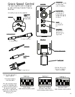
10-1: Attach the Right Handle Tube to the right back
corner of the Top Plate with two (2) 6mm X 10mm SBHC
Screw, as shown in Fig (10-1).
10-2: Attach the Left Handle Tube to the left back corner
of the Top Plate with two (2)6mm X 10mm SBHC Screws,
as shown in Fig (10-1).
10-3: Attach the Handle Brace onto both the Right & Left
Handle Tubes with two (2) 6mm X 40mm SBHS,
as shown in Fig (10-2).
Step 11: Bottom Plate Assembly
Parts Needed:
1- Bottom Plate
1-Bottom Plate Platform
2- Bottom Plate Extrusion End Cap A’s
2- Bottom Plate Extrusion End Cap B’s
11-1: Push two (2) Bottom Plate Extrusion End Cap A’s
into opposite corners of the Bottom Plate. Make sure
both End Cap A’s slide into the slots on the Bottom
Plate Extrusions as shown in Fig (11-1).
11-2: Push two (2) Bottom Plate Extrusion End Cap
B’s into the remaining two corners of the Bottom Plate.
Make sure both End Cap B’s slide into the slots on the
Bottom Plate Extrusions.
11-3: Remove the backing from the Double Sided Tape
that is attached to the Bottom Plate Extrusion.
11-4 Apply the Bottom Plate Platform to the Bottom
Plate. Press edges firmly into place until the platform
has adhered completely into place, as shown in Fig
(11-2).
Step 12: Bottom Plate Placement
Parts Needed:
1- Bottom Plate Assembly
1- Table Assembly - Complete
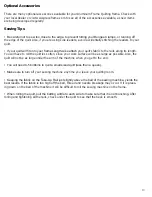
12-1: First, remove the Take-Up Rail from the Table
Assembly. This is the Rail located over the middle of the
table.
12-2: Place the Bottom Plate Assembly on the Table
Assembly and make sure that all four wheels on the
Bottom Plate are in contact with the Plastic Track. The
Bottom Plate should roll smoothly on the Track.
Fig (10-2)
Fig (11-1)
Fig (11-2)
Fig (12-1)