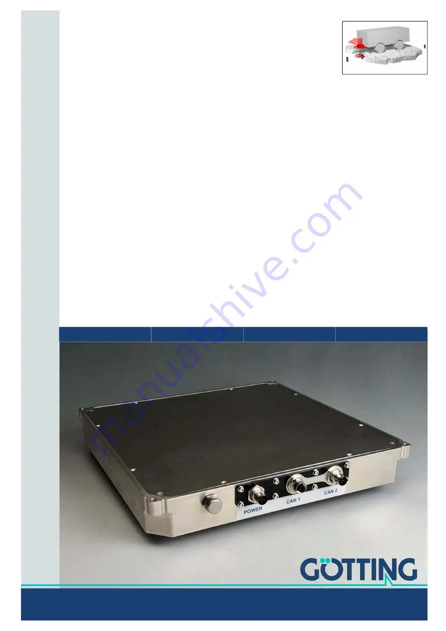
Gotting HG G-98830 Скачать руководство пользователя страница 1

Transponder Antenna

HG G-98830YA

2-dimensional Position Detection & Identification

Outdoor, flat Design

English, Revision 02

Date: 21.06.2021

Dev. by: WM

Author(s): RAD / AF

Operating Manual HG G-98830YA

Transponder

Innovation through Guidance

www.goetting-agv.com

Содержание HG G-98830

Страница 1: ...830YA 2 dimensional Position Detection Identification Outdoor flat Design English Revision 02 Date 21 06 2021 Dev by WM Author s RAD AF Operating Manual HG G 98830YA Transponder Innovation through Gui...

Страница 2: ...1 A when programming transponders typically 300 mA 24 V Connectors 3 x M12 5 pin A coded 1x Power incl serial RS 232 PosiPulse 2x CAN CAN module according to CAN specification V2 0 part B standard ext...

Страница 3: ...ransponders 16 4 2 2 Structure of the Transponder Code 17 4 3 Transponder Antenna 17 5 Operating Principle 18 5 1 Position Detection with Transponders 18 5 2 Track Guidance with Transponders 19 5 3 Po...

Страница 4: ...Data Objects SDOs 46 9 5 5 Object Directory 47 10 Configuration of the System via the Service Interface 48 10 1 Starting the Monitor Program 48 10 1 1 Procedure Monitor Only 48 10 1 2 Procedure 3964R...

Страница 5: ...2 Error Register 92 16 5 3 COB ID SYNC Message 92 16 5 4 Device name 92 16 5 5 Hardware Version 92 16 5 6 Software Version 92 16 5 7 Save Parameters 93 16 5 8 Restore Default Parameters 93 16 5 9 Pro...

Страница 6: ...n in another way qualified persons who integrate the transponder antenna into a vehicle or mobile robot put it into operation for the first time or configure it 1 1 2 Additional Applicable Documents T...

Страница 7: ...description uses consistent warning notices symbols terms and abbreviations Those are described in the following sections 1 3 1 Warning Notices In these operating instructions warnings are given befo...

Страница 8: ...es are indicated through the use of a fixed width font Menu items and parameters are shown in cursive characters Whenever the pressing of letter keys is required for program entries the required etter...

Страница 9: ...has to point towards the ground Figure 1 Figure 1 Reading and mounting side of the transponder antenna 1 4 2 Coordinate System of the Antenna The signs and coordinates given in this operating manual a...

Страница 10: ...ns Table 2 Abbreviations Abbreviation Meaning CAN Controller Area Network CANopen Controller Area Network open EDS Electronic Data Sheet AGV Automated Guided Vehicle PDO Process Data Object RFID Radio...

Страница 11: ...ots or electric monorail conveyors i e the transponders move the antenna is located at a fixed posi tion The field of application of the transponder antenna HG G 98830YA is the position detection of A...

Страница 12: ...transponder antenna if this is part of their activi ties is in case the CAN bus interface is to be used familiar with the commission ing of and telegram exchange via CAN bus connections knows in the...

Страница 13: ...e g splash water from the wheels of the vehicle and cleaned regularly otherwise wear and tear on the antenna will increase 2 5 Obligations of the Operator When using the transponder antenna the operat...

Страница 14: ...ee Preparation of Con nection Cables or ordered from G tting see below No G tting cables are available for the Profinet interface Refer to Table 3 for the order numbers of the required accessories Tab...

Страница 15: ...Optional accessories Order No Description HG G 81840ZA Transponder programming device for reading and programming of transponder codes The transponders can also be programmed via the antenna but this...

Страница 16: ...controller for calculating the paths of the vehicle we recommend the navigation controller from G tting Figure 3 System components excerpt 4 2 Components in the Ground 4 2 1 Transponders Transponders...

Страница 17: ...e code telegram is 8 ms 4 3 Transponder Antenna Figure 4 Transponder antenna HG G 98830YA The antenna systems including preamplifier and evaluator are built into one housing All cable connections are...

Страница 18: ...moving over a course Alternatively the antenna may be mounted at a fixed position and the plant part with transponder moves relative to it e g an arm of a robot or an electric monorail In the followin...

Страница 19: ...From this a downstream navigation system uses the circumfer ence of the wheels and the steering angle to calculate the distance traveled and the orientation of the vehicle Odometry has the advantage...

Страница 20: ...k guidance free navigation with transponders For path planning a driving course consisting of segments is stored in the navigation controller This course is subdivided into virtual support points whic...

Страница 21: ...ng into account the technical capabilities of the vehicle possible curve radii wheel diameters maximum speed etc it calculates routes and can thus tell the vehicle computer in which direction and at w...

Страница 22: ...storage temperature is 20 C to 60 C Store the device in closed rooms only Make sure that the storage room is sufficiently ventilated and dry Protect the device from damage caused by dirt dust or mois...

Страница 23: ...ating Conditions for Transponders Transponders must not be permanently mounted in standing water The plastic can absorb water over a longer period of time and weaken the transponder signal Reinforceme...

Страница 24: ...the positioning pulse is supplied via Ub 24 V and is limited to 20 mA If you want to use the serial interface Please refer to Chapter 10 Configuration of the System via the Service Interface on page...

Страница 25: ...r de tails The transponder antenna must be mounted firmly on the vehicle so that its position cannot change during normal operation Otherwise the position data will be incor rectly evaluated by the hi...

Страница 26: ...mm If you suspect that magnetic fields are transmitted via the chassis construction If in doubt carry out tests before assembly 7 3 4 Minimum Distance to Current Carrying Wires Around the Transponder...

Страница 27: ...on page 28 Figure 12 shows a connection example Figure 12 Connection example No metal allowed in this area 50 mm No metal loops allowed in this area 300 mm POWER CAN 1 CAN 2 Transponder antenna CAN b...

Страница 28: ...ngs for dowel pins on the vehicle which can optionally be used to facilitate positioning during installation If you want to use dowel pins Provide at least four dowel pins on diagonally opposite sides...

Страница 29: ...vehicle floor or a mounting plate through which M6 screws are screwed into the threads of the antenna holes from the vehicle Figure 16 Mounting with M6 screws 4x M5 Screw The M5 screws are fed throug...

Страница 30: ...ntenna software first waits 10 seconds During this time you can start a firmware update see 10 2 15 U pdate Firmware on page 72 After this time the actual antenna program starts If you have configured...

Страница 31: ...Antenna Monitor Program on page 33 Saving the values and restarting the system see 8 4 Finish Commissioning on page 33 8 1 Connecting the Antenna to a Computer You can configure the system using a sof...

Страница 32: ...in the terminal program If you are using another port than COM1 and you are using HyperTerminal then change the port as follows In the File menu select the Properties subitem or click on the Icon The...

Страница 33: ...interference must not exceed 100 units The influence of the interferences strongly depends on the level of the transponder signal The transponder signal must be clearly above the interference signal T...

Страница 34: ...Operating Manual HG G 98830YA English Revision 02 Date 21 06 2021 34 Chapter 8 Commissioning If you need a reference file for later settings Archive the file see 10 2 17 P r int Parameters on page 73...

Страница 35: ...o potential separa tion For safety reasons a 20 mA current limit is implemented in the antenna for this output If for example a 24 V voltage output is required pin 2 can be connected to GND via a resi...

Страница 36: ...ut first or the low byte is output first The 8 bit checksum is only output when using the transparent protocol and includes the start character You cannot remove the start character as well as the che...

Страница 37: ...des are read 0x0008 0x0010 EEPROM_ERROR Parameter E Prom not addressable 0x0020 PARAM_CRC_ER Parameter set no longer safe 0x0040 POT_ERROR IIC bus potentiometers not addressable 0x0080 F_ERROR Transmi...

Страница 38: ...a PLC as the sub sequent output is no longer in accordance with transparent or 3964R protocol but is only suitable for display on a VT52 terminal and is used to change parameters manually d Table 10...

Страница 39: ...16 3D16 ASCII ST 07 10 3964R HEX 53165416 30163816 Set tuning value to 8 ASCII ST 08 transparent HEX 3D16 53165416 30163816 3216 ASCII ST 08 2 11 3964R HEX 53165416 30163916 Set tuning value to 9 ASCI...

Страница 40: ...X 53165016 0 3E816 Set positioning level 0 level 1024 ASCII SP transparent HEX 3D16 53165016 0 3E816 ASCII SP Checksum in this case depending on the values used Examples Level should be set to 1000 3E...

Страница 41: ...magic com 22 3964R HEX 50164816 Code in the format tt16tt16 For code 1234 e g 12163416 Transmission of the most significant bits of the tran sponder code to be pro grammed and start of programming ASC...

Страница 42: ...st Sync telegram Synchronous Data is transmitted after receipt of a sync telegram Asynchronous Data is transmitted event driven RTR Only on request by a remote frame Inhibit Time Minimum time period w...

Страница 43: ...re of the CAN Message Object Y Identifier Byte Length Type Meaning 1 2 2 Byte unsigned int System status notes according to Table 9 on page 37 3 4 5 6 4 Byte unsigned long 20 bit transponder code R W...

Страница 44: ...d one time programming process takes 100 to maximum 200 ms Afterwards the new code can be read out in the corresponding message object If the programming process was not successful you must repeat the...

Страница 45: ...ant bit in the associated PDO COB identifier PDO_1 is transmitted with identifier 0x180 node address It contains 8 bytes which include the status from the monitor program The transmission order is sta...

Страница 46: ...oes not monitor the reg ular input of RTR frames 9 5 4 Description of Service Data Objects SDOs The service data object is used for accesses to the object directory An SDO is trans mitted acknowledged...

Страница 47: ...ed in section 16 4 Overview of the CANopen Directory on page 89 Table 26 Possible error codes SDO telegram Name Number Meaning SDO_ABORT_UNSUPPORTED 0x06010000 Unsupported access to a Object SDO_ABORT...

Страница 48: ...10 1 1 Procedure Monitor Only If the antenna is set to the procedure Monitor only the monitor mode will be started 10 s after the system is activated In this case you do not need to transfer any file...

Страница 49: ...ed to procedure 3964R with LowByte first The file contains the following characters in hexadecimal notation 0x02 0x4F 0x4D 0x49 0x4E 0x10 0x03 0x16 3 Montrans txt Transfer this if the system is switch...

Страница 50: ...the serial interface switches back to the configured 3964R or transparent output NOTICE Modifying the antenna parameters may detune the antenna The changes to the antenna parameters described below c...

Страница 51: ...he number of code readings per transponder crossing max 255 The value is held until a new transponder is detected Is also deleted by Noise N The number of reading errors per transponder crossing The v...

Страница 52: ...om see 10 2 14 on page 71 pdate Firmware see 10 2 15 on page 72 Import Export User Parameter see 10 2 16 on page 72 P int Parameters see 10 2 17 on page 73 10 2 4 Setting and Permanently Saving Parame...

Страница 53: ...19200 Baud 38400 Baud To switch the baud rate Press the key and enter the desired value Setting the procedure for telegram transmission The parameter P rocedure is used to set the procedure for the m...

Страница 54: ...ddition The sequence of the parameters cannot be influenced It always corresponds to the sequence in Table 8 on page 36 Value range 0 1FFF see column Value Table 8 on page 36 The length of the telegra...

Страница 55: ...time Value range 1 1680 ms To adjust the acknowledgment delay time Press the key and enter the desired value Setting the output type With the parameter Conti n ous Telegrams you determine whether data...

Страница 56: ...can be transmitted at the selected baud rate in the set time see Figure 21 on page 36 Press the key and enter the desired value Freezing the telegram output With the parameter F reeze Values for n Te...

Страница 57: ...minimize inter ference If you use the positioning channel the code is dropped in the middle at x 0 in a narrowly defined area The error counter N and the noise counter increase the bit Noise and wrong...

Страница 58: ...ossing speed as the re quired transmission time will increase with n 1 x 8 ms Value range 0 15 To define the number of codes to be compared Press the key and enter the desired value Setting the voltag...

Страница 59: ...Value range n 1 ms To determine the duration of the positioning pulse Press the key and enter the desired value Setting the number of positioning pulses With the parameter O ne Positioning Pulse per C...

Страница 60: ...0 The CODE_OK Bit is switched to the output 1 The positioning pulse is switched to the output To select this function Press the key To switch this function off again Press the key again Setting the th...

Страница 61: ...r internal test purposes In practice 1553000 Hz or 1575000 Hz have proven to be optimal To set the receive frequency Press the button and enter the desired value Activating Autotuning With the paramet...

Страница 62: ...The transmitter is switched on for control purposes To switch the transmitter on or off for control purposes Press the key and enter the desired value 10 2 8 Basic C A N Parameters In the Basic C A N...

Страница 63: ...rameter E xtended CAN you can generate telegrams as standard frames according to CAN 2 0A 11 bit value or as extended frames according to CAN 2 0B 29 bit value Selection STANDARD EXTENDED IDs To selec...

Страница 64: ...idth Tseg 1 and Tseg 2 you can adjust the Bit timing Value ranges B R P Baudrate Prescaler 0 63 S J W Sync Jump Width 0 3 Tseg 1 2 15 Tseg 2 1 7 To adjust the Bit Timing Press the keys or and enter th...

Страница 65: ...To select this function Press the key To switch this function off again Press the key again Freeze telegram output With the parameter F reeze Values for n Telegrams you can freeze the output of the Y...

Страница 66: ...nterface is not connected or no CAN termination is installed Furthermore the CAN open node states stopped preoperational or operational are displayed The information can be used for simple diagnostics...

Страница 67: ...oltages are transmitted Value range 1 240 255 To select the synchronous cyclic mode Press the keys or and enter a value between 1 and 240 To select the asynchronous mode Press the keys or and enter th...

Страница 68: ...the heartbeat message will be transmitted if it is activated The antenna changes to mode preoperational 1 Autostart is activated After power on the heartbeat message if it is acti vated and the PDOs w...

Страница 69: ...mstatus Press the key To exit the display Press the key The main menu is shown 10 2 11 Cs v Figure 31 Example of a CSV text file For diagnostic purposes you can output the following values in CSV form...

Страница 70: ...sed under HyperTerminal Open the CSV file in a spreadsheet e g Microsoft Excel OpenOffice Calc You can now format the data in chart form see Figure 32 or save them as native spreadsheet file for furth...

Страница 71: ...splayed in mm To exit the menu Press any key The main menu is shown 10 2 13 W rite Transponder The W rite Transponder menu allows you to program transponders in the antenna field at nominal reading di...

Страница 72: ...open Open the Flash program In the flash program select the COM port with which the antenna is currently connected to your PC Choose the HEX file you want to program Now go back to HyperTerminal and...

Страница 73: ...starts Alternatively you can export the data using the HyperTerminal monitor program as follows Choose Transfer Receive file XMODEM Select folder from the menu and enter a file name After a successfu...

Страница 74: ...ogram described below We will send this to you by e mail on request Send your request by e mail phone fax or letter to the address mentioned on the title page The program for updating the antenna soft...

Страница 75: ...e file will be transferred If an error occurs during the transfer status messages colored red are output As long as only green messages appear 5 the software update is proceeding correctly The last 2...

Страница 76: ...check the functionality of the antennas you must regularly check the current con sumption and the voltage supply To do so please use the values in the menus of the monitor program For keeping the ant...

Страница 77: ...with the legal requirements of your country For EU countries only Do not dispose of the transponder antenna in household waste Collect used electrical equipment separately in compliance with European...

Страница 78: ...if necessary Wrong transmission procedure selected Wrong transmission parameters set Select only 19200 or 38400 Baud 8 Bit even parity Wrong transmission parameters set Set the correct procedure etc...

Страница 79: ...transponders correctly but is not af fected by interference on the entire driving course as far as possible we recommend adjusting the following values Level to Noise Error Threshold for Decoding Leve...

Страница 80: ...ntire driving course you must log a complete drive over the facility For setting the positioning thresholds you can use the serial interface of the antenna see 9 2 Serial Interface RS232 on page 35 or...

Страница 81: ...hreshold once If the positioning thresholds are set too low the antenna may receive new transponder signals but not output them Set the positioning thresholds on the basis of the recorded values in su...

Страница 82: ...est drive over several transponders Antenna width Side lobes before the transponder is under the antenna Threshold position detection e g 500 units Uref Transponder Code Recommended threshold in this...

Страница 83: ...with HW DEV00095 HW DEV00098 40 to 80 mm with HG G 71325XA Nominal reading distance 50 mm Static positioning accuracy 1 2 mm at nominal reading distance within 90 mm around antenna centre with HG G 7...

Страница 84: ...ting resistor Terminator not integrated Full CAN Basic CAN according to ISO DIS 11898 Identifier Data rate Standard Extended Frames adjustable via serial interface CANopen CANopen Device Profil DS 401...

Страница 85: ...of the antenna with dimensions 2 1 G TTING K G S ensortechnik D 31275 L e h r t e Zng Prj Teil von Gez SZ 21 11 13 NameDatum 12546 Rev 01 Toleranz wenn nicht anders vermerkt DIN ISO 2768 m 98830 Geh...

Страница 86: ...racy of the distance calculation in X direction driving direction with Transponder HW DEV00095 0 100 200 300 400 500 600 700 800 900 1000 130 110 90 70 50 30 10 10 30 50 70 90 110 130 Antenna HG G 988...

Страница 87: ...stop bit baud rate 38400 baud default or 19200 baud 16 2 1 Data Direction Antenna PLC Antenna data are transmitted cyclically from the antenna to the PLC The data record always starts with an characte...

Страница 88: ...e 43 State diagram procedure 3964R PLC Antenna 16 3 Procedure transparent For the connection antenna PLC you can also us the transparent protocol You must observe the following settings for data trans...

Страница 89: ...The telegram must be terminated with an 8 bit check character over all characters incl start character The charac ters must be received within the parameterizable character delay time Otherwise the t...

Страница 90: ...ime C 0x1A00 0 RO Number of Objects mapped to Transmit PDO_1 1 RO Specification of Appl Object 1 2 RO Specification of Appl Object 2 3 RO Specification of Appl Object 3 0x1A01 0 RO Number of Objects m...

Страница 91: ...page 60 a RW Freeze values for n telegrams M 10 2 9 page 65 b RW Threshold max detection X Y M 10 2 6 page 56 c RW Config M Table 52 page 98 0x2001 0 RO Number of Parameter 1 RW Node Baudrate C 2 RW N...

Страница 92: ...ame Type Attr Map Default Description 0x1001 00 Error Register Unsigned 8 RO No 0x00 Error Register Table 37 CANopen directory COB ID SYNC message Index Subindex Name Type Attr Map Default Description...

Страница 93: ...me With 0 this function is switched off Table 41 CANopen directory Save parameters Index Subindex Name Type Attr Map Default Description 0x1010 00 Save Parameter Unsigned 8 RO No 0x01 number of subin...

Страница 94: ...r Index Subindex Name Type Attr Map Default Beschreibung 0x1800 00 TxPDO_1 Parameter Unsigned 8 RO No 0x05 Number of subindexes 01 COB ID Unsigned 32 RW No 0x40000180 Node ID PDO_1 valid ID 0x180 Node...

Страница 95: ...p Default Description 1A00 00 Number of mapped objects Unsigned 8 RO No 0x03 Number of subindexes 01 1st mapped object Unsigned 32 RO No 0x61000110 mapped on index 0x6100 01 with 16 bit length status...

Страница 96: ...bit length SUM voltage 02 2nd mapped object Unsigned 32 RO No 0x64010410 mapped on index 0x6401 04 with 16 bit length DIF voltage 03 3rd mapped object Unsigned 32 RO No 0x60000108 mapped on index 0x6...

Страница 97: ...6 page 56 04 Poispulse time Unsigned 16 RW No 100 10 2 6 page 56 05 High nibble of RW code Unsigned 8 RW No 16 10 2 6 page 56 06 Number of equal codes Unsigned 8 RW No 1 10 2 6 page 56 07 Level to no...

Страница 98: ...e positioning pulse per transponder crossing see 10 2 6 T ime Code on page 56 0x0400 AUTO_TUNE see 10 2 7 F requency Antenna Tuning on page 60 0x0800 0x1000 0x2000 POSI_TRNSP Positioning pulse after d...

Страница 99: ...Nopen directory 16 bit status transmission in TPDO_1 Index Subindex Name Type Attr Map Default Description 0x6100 00 number of 16 bit inputs Unsigned 8 RO No 0x01 number of 16 bit inputs 01 16 bit dig...

Страница 100: ...s without any time delay Positioning coil Coil for receiving the transponder signal arranged in such a way that the signal at the center axis of the antenna has a characteristic course in the directio...

Страница 101: ...Figure 17 Mounting with M5 Screws 29 Figure 18 Example of connection Connection to the serial interface of a computer 31 Figure 19 Setting the COM port in HyperTerminal 32 Figure 20 Connection option...

Страница 102: ...ical accuracy of the distance calculation in X direction driving direc tion with Transponder HW DEV00095 86 Figure 41 Typical accuracy of the deviation calculation in Y direction transverse to the dir...

Страница 103: ...Structure of the CAN Message Object D Identifier 43 Table 19 Structure of the CAN Message Object Programming 44 Table 20 Coding of the commands CAN Message Object Programming 44 Table 21 Variables in...

Страница 104: ...ectory Mapping TPDO_1 95 Table 49 CANopen directory Mapping TPDO_2 95 Table 50 CANopen directory Mapping TPDO_3 96 Table 51 CANopen directory Device parameters 97 Table 52 CANopen directory Relevant c...

Страница 105: ...ntifier 43 CAN1 25 CAN2 25 CANopen 44 66 directory 89 setting the baud rate 67 checking the generated telegram 54 checking the highest four bits for a preset value 0 F 58 commissioning 31 company name...

Страница 106: ...15 20 navigation system 20 nibble 100 Node Guarding 46 nominal reading distance 25 O object directory 89 object index 89 obligations of the operator 13 odometry 19 100 operating conditions antenna 25...

Страница 107: ...g the threshold for generating the RX_NOISE bit 57 setting the threshold for the scan coils 60 setting the timeout time transparent 55 setting the voltage for code decoding and position calculation 58...

Страница 108: ...f the systems are used according to the description This instruction manual has been drawn up to the best of our knowledge Installa tion setup and operation of the device will be on the customer s own...

Страница 109: ...Operating Manual HG G 98830YA English Revision 02 Date 21 06 2021 109 Copyright and Terms of Liability Chapter 20...

Страница 110: ...Innovation through Guidance G tting KG Celler Str 5 D 31275 Lehrte Tel 49 0 5136 8096 0 Fax 49 0 5136 8096 80 info goetting agv com www goetting agv com www goetting agv com...

Отзывы: