background image

GHS SERIES

OM--05450

PAGE E--11

MAINTENANCE AND REPAIR
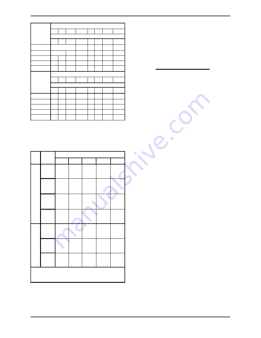
GC,GF,GH,GJ

.004

.006

.008 .006

.008

.010

JG,JJ,JL,JP

.004 .006 .008

.010 .006 .008

.010

.012

NK,NM,NP

.006 .006 .008

.010 .006 .008

.010

.012

RM,RP,RR,RS

006 .008 .010

.012 .008 .008

.010

.014

Dimensions are shown in inches. For Viscosities Above

250,000 SSU, or Other Special Applications, Consult Your

Local Gorman-Rupp Distributor or the Factory.

750 2500 25,000 250,000 750 2500 25,000 250,000

225 225 225

225

400 400

400

400

Max. Visc. (SSU)

Max. Temp. (

_

_

_

_

F)

HYD. SIZE

Notes:

GC,GF,GH,GJ .006

.008

.010 .008

.010

.012

JG,JJ,JL,JP

.006 .008 .010

.012 .008 .010

.012

.014

NK,NM,NP

.008 .008 .010

.012 .010 .010

.012

.014

RM,RP,RR,RS

008 .010 .012

.014 .010 .010

.012

.016

750 2500 25,000 250,000 750 2500 25,000 250,000

525 525 525

525

675 675

675

675

Max. Temp. (

_

_

_

_

F)

Max. Visc. (SSU)

HYD. SIZE

Table E-1. End Clearance Based on Hydraulic

Size, Viscosity and Temperature

Rotor

Trim

Code

V

i

s

c

o

s

i

t

y

T

r

i

m

s

Pump Hydraulic Code

Std

.005

.005

.006

.006

.008

D

G

J

N

R

35B

.005

.005

.006

.006

.008

35C

.005

.006

.008

.008

.010

35D

.009

.009

.012

.012

.015

T

e

m

p

T

r

i

m

s

35E

.005

.010

.014

.014

.016

35J

.006

.012

.016

.016

.018

35N

.014

.014

.018

.018

.020

Notes:

For Rotor Trim Codes Not Listed or for Special Applications,

Consult Your Local Gorman-Rupp Distributor or the Factory.

Consult Pump Parts List For Rotor Trim Code.

Table E-2. End Clearance Based on Rotor

Trim Code

RELIEF VALVE DISASSEMBLY

(Figure E-7)

NOTE

If the relief valve is low pressure, it will have one in-

ternal spring (10AE). If the relief valve is high pres-

sure, it will have two internal springs (10AE and

10AF).

Unscrew the cap (10AN) from the bonnet (10AK).

Remove the optional gasket (10AP, if so equipped).
Back off the adjustment capscrew (10AM) to re-
lieve pressure on the spring(s) (10AE and/or

10AF).

Unscrew the bonnet from the valve body (10AA)
and remove the gasket (10AJ) or O-ring (10C). Re-

move the valve (10AD) and spring(s) (10AE and/or
10AF). The spring guide (10AH) is an O-ring fit in
the bonnet. Remove and discard the O-rings.

If the warning plate (10AB) must be replaced, re-
move the drive screws (BM), and remove the plate.

Содержание GHS Series

Страница 1: ...NY MANSFIELD OHIO www gormanrupp com GORMAN RUPP OF CANADA LIMITED ST THOMAS ONTARIO CANADA Printed in U S A Copyright by the Gorman Rupp Company INSTALLATION OPERATION AND MAINTENANCE MANUAL ROTARY GEAR PUMPS MODELS GHS SERIES IRON AND STEEL PUMPS G J N R SIZES ...

Страница 2: ...NG PAGE B 6 General Rules of Tensioning PAGE B 6 Tension Measurement PAGE B 6 ELECTRICAL CONNECTIONS PAGE B 7 OPERATION SECTION C PAGE C 1 PUMP OPERATION PAGE C 1 PRE OPERATION PAGE C 1 Before Starting the Pump PAGE C 1 Checking Pump Rotation PAGE C 1 STARTING PAGE C 2 OPERATION PAGE C 2 Liquid Temperature PAGE C 2 Overheating PAGE C 2 Checking Gauges PAGE C 2 Strainer Check PAGE C 3 Leakage PAGE ...

Страница 3: ... 02 PAGE E 9 Optional Head Jacket PAGE E 9 Coverplate Kit 11 PAGE E 9 Foot Bracket Kit 08 PAGE E 9 Rotor Adjusting Sleeve 07 PAGE E 9 SETTING END CLEARANCE PAGE E 10 RELIEF VALVE DISASSEMBLY PAGE E 11 RELIEF VALVE REASSEMBLY PAGE E 11 Relief Valve Installation 10 PAGE E 13 SEAL APPENDIX SECTION F PAGE F 1 Standard Friction Drive And Optional 60A 60B And 61J Mechanical Seals PAGE F 1 Positive Drive...

Страница 4: ... with a drive unit refer to the drive unit manufacturer s installation and oper ation instructions in the literature accompanying the pump These pumps can transfer a wide range of light medium and heavy viscosity liquids depending on design and components Some models are not recommended for use with water others when fitted with specific options may be used with water consult the factory If there ...

Страница 5: ...result from failure to follow the procedure Hazards or unsafe practices which COULD result in severe personal injury or death These instructions describe the procedure required and the injury which could result from failure to follow the procedure Hazards or unsafe practices which COULD result in minor personal injury or productor property damage These instructions de scribe the requirements and t...

Страница 6: ...mpting to install operate or service this pump familiarize yourself with this manual and with all other liter ature shipped with the pump Unfamil iarity with all aspects of pump operation covered in this manual could lead to de struction of equipment injury or death Depending on design and components this pump will handle a wide range of light medium and heavy viscosity liq uids at a variety of te...

Страница 7: ...mp will remain inoperative 3 Allow the pump to completely cool if overheated 4 Close the discharge and suction valve if used An overheated pump can cause severe burns and injury If overheating occurs 1 Stop the pump immediately 2 Allow the pump to completely cool 3 Refer to the instructions in this manual before restarting the pump Do not remove plates covers gauges pipe plugs or fittings from an ...

Страница 8: ...upp rotary gear pumps Rotary gear pump model numbers include design style port size hydraulic size and construction code Typical Pump Model GHS 1 1 2 GF 32 Design Style Port Size Hydraulic Size Construction Code Design Style Gorman Rupp rotary gear pumps are available in five basic designs S GMC Medium Duty Compact S GMS Medium Duty S GHC Heavy Duty Compact S GHS Heavy Duty S GHA Abrasive Duty Por...

Страница 9: ... the pump will oc cur a Do not flush the pump Ensure that the port plugs shipped with the pump remain in place until piping is installed to help prevent dust or other foreign objects from entering the pump b Pumps that will not be installed for an ex tended period should be stored indoors if possible The factory installed port plugs will not ensure protection from excessive humid ity splash water ...

Страница 10: ...nting the base on a foundation Mount the base on a foundation that will provide permanent rigid support for the pump and will be heavy enough to absorb any vibration strain or shock Piping Before establishing suction and discharge lines determine pump port positions and rotation Fig ure B 1 shows typical port positions for the stan dard 90_ housing if you have selected a 180_ housing port option y...

Страница 11: ...stall a shut off valve in the discharge line particularly on a flooded suction application Shutoff valves are not recommended for suction lines It is not recommended that a foot valve be installed at the end of the suction line If desired to install a foot valve consult the factory When handling very hot or cold liquids install a pressure relief valve in any part of the system that can be valved o...

Страница 12: ...nt when the hubs are the same distance apart at all points see Figure B 3 Figure B 3 Aligning Non Spider Type Coupling Check parallel adjustment by laying a straightedge across both coupling rims at the top bottom and side When the straightedge rests evenly on both halves of the coupling the coupling is in horizontal parallel alignment If the coupling is misaligned use a feeler gauge between the c...

Страница 13: ...tion to belt span is 1 64 for both ASA and metric units Therefore a belt with a span of 64 inches would require a deflection of 1 inch at the force shown on the Tables for your particular application For example if the span as measured in Figure B 5 is 32 inches 813 mm the v belt cross section isC the smallest sheave diameter is 8 inches the pump speed is 1250 RPM and the belts are uncogged Yy T t...

Страница 14: ...nge R P M Range Used Belt New Belt Used Belt New Belt Belt Deflection Force Uncogged Hy T Belts Uncogged Hy T Torque Team Cogged Torque Flex Machined Edge torque Team Belts A AX 75 90 1000 2500 2501 4000 1 7 1 3 2 5 1 9 1 9 1 5 2 8 2 3 91 120 1000 2500 2501 4000 2 0 1 7 3 1 2 6 2 3 2 0 3 4 2 9 125 175 1000 2500 2501 4000 2 4 2 1 3 6 3 2 2 6 2 3 4 3 3 4 B BX 85 105 860 2500 2501 4000 2 2 1 9 3 3 2 ...

Страница 15: ...proof motor in an explosive atmo sphere Install connect and operate the motor in accordance with The Na tional Electrical Code and all local codes If there is a conflict between the instructions in the manual accompany ing the unit and The National Electrical Code or the applicable local code The National or local code shall take prece dence ...

Страница 16: ...th a packing seal loos en the gland nuts before starting until the packing gland may be moved slightly If leakage seems ex cessive after starting wait until the pump has run long enough to reach its normal operating temper ature to adjust the gland nuts Packing pumps must leak slightly to cool and lubricate the shaft and to allow the shaft to turn freely Consult the drive manufacturer s operating ...

Страница 17: ... factory OPERATION NOTE If the pump malfunctions or does not meet operat ing specifications refer to TROUBLESHOOTING Section D A change in operating noise when liquid first enters the pump is normal After the pump is fully opera tional monitor it for any unusual noises or vibra tion if either occurs shut the pump down immedi ately Liquid Temperature Do not install the pump in a service with higher...

Страница 18: ...t provided with a pressure re lief valve A pressure relief valve must be installed on the pump or in the discharge piping to ensure safe operation Otherwise the pump may be dam aged and personnel injured If operating at high temperatures allow the pump to completely cool before attempt ing any adjustments Cracking Pressure Cracking pressure is the pressure at which the pressure relief valve first ...

Страница 19: ...en handling non lu bricating liquids drain the system and flush the pump and piping with an oil based preservative to protect close tolerance pump parts When handling liquids that solidify when at rest tar glue etc flush the pump and piping with an approved solvent compatible with the pump com ponents and the liquids being pumped ...

Страница 20: ...ne blocked foot valve jammed strainer blocked Liquid too viscous Lift too high Suction line undersized LOW READING Air leak in suction line End of suction line not submerged Pump parts worn or defective End clearance too great No liquid in pump housing ERRATIC READING Liquid overheated vaporizing Liquid entering intermittently suction air leak end of suction line not submerged Vibration from cavit...

Страница 21: ...e not submerged foot valve blocked or jammed insufficient liquid in sump or tank Check vacuum gauge disassemble pump and replace faulty parts Relief valve pressure set too low Housing dry Add liquid to housing see OPERATION SECTION C Rotating parts worn or damaged im proper end clearance Replace defective parts see SETTING END CLEARANCE in Maintenance And Repair Section E Pump speed too slow Check...

Страница 22: ...uired Add lubricant as needed Corrosive liquid Check local distributor or factory for parts compatibility with liquid check liq uid for contamination EXCESSIVE WEAR Exceeding operating limits Check performance data in Pump Speci fications Bulletin Insufficient end clearance See SETTING END CLEARANCE in Maintenance And Repair Section E Pump running dry Add liquid to prime See Operation Sec tion C c...

Страница 23: ...regular intervals of 2000 hours Critical applications should be in spected more frequently Check the thrust washer medium duty models idler bushing idler pin idler assembly shaft bush ing and rotor shaft assembly at each inspection Wear patterns should be uniform without evi dence of deep or irregular grooves For packing pumps periodic adjustment of the packing is required to keep leakage to a min...

Страница 24: ...pump Below the pump model number on the Parts List is a grouping of several alpha numeric codes This code identifies the optional components of the pump Contact the Gorman Rupp Company to verify performance and options The following illustrations cover disassembly and reassembly for the pump models shown below Refer to the Parts List for your specific pump model The Following Pumps Are Covered By ...

Страница 25: ...nal Foot Bracket Also Available With 180_ Ports And Or Jacketed Seal Head Jacket Housing Mounted Relief Valve A Coverplate Kit Replaces Either Relief Valve When Not Used NOTE Refer to Seal Appendix Section F for details of the Seal Assembly and Related Components 46167302 Figure E 1 Typical GHS G J N And R Size Pump Models ...

Страница 26: ...R ADJUSTING SLEEVE ASSY 07AA ROTOR ADJUSTING SLEEVE 07AC BALL BEARING 07AD BEARING RETAINING NUT GA SOCKET HD SETSCREW 07AJ BRG SPACER IF REQUIRED 07F O RING IF REQUIRED 07H RETAINER CLIP IF REQUIRED 07L SEAT SLEEVE IF REQUIRED 07S SEAT SLEEVE IF REQUIRED 07V O RING IF REQUIRED 08 FOOT BRACKET KIT 08A FOOT BRACKET B CAPSCREW D NUT 10 RELIEF VALVE KIT 10A RELIEF VALVE ASSEMBLY 10AA VALVE BODY 10AB ...

Страница 27: ...e it is the responsibility of the owner installer and or maintenance personnel to en sure that applications and or mainte nance procedures not addressed in this manual are performed only after estab lishing that neither personal safety nor pump integrity are compromised by such applications or procedures Do not attempt to service the pump un less all power to the power source has been disconnected...

Страница 28: ... binds against the head This will prevent the rotor from turning as the lock nut is unscrewed Straighten the tab on the bearing lockwasher 03B and use a hammer and drift pin to loosen the bear ing locknut until it can be unscrewed from the shaft Remove the bearing lockwasher Unscrew the rotor adjusting sleeve kit from the backhead NOTE Part or all of the seal assembly 05 may be re moved with the r...

Страница 29: ...sembled idler 02 from the head as sembly Inspect the idler bushing 02B for exces sive wear or scoring If replacement is required use an arbor or hydraulic press to remove the idler bushing from the idler To remove the idler pin 01AB lay the head as sembly 01A on an arbor or hydraulic press with the idler pin facing down and press the idler pin from the head Seal Removal 05 The seal assembly 05 is ...

Страница 30: ...s printed on solvent containers Clean and inspect the pump parts except the bearing and seal assembly with a cloth soaked in fresh cleaning solvent Inspect all parts for exces sive wear or for any nicks or burrs Remove nicks or burrs using emery cloth or a fine file Replace any parts that are badly worn or damaged Rotate the bearing by hand to check for roughness or binding If rotation is rough or...

Страница 31: ...t to the discharge port and install one of the larger diameter pipe plugs over the smaller one Install the second large pipe plug in the other hole in the back of the hous ing adjacent to the suction port Backhead Kit 06 Figures E 1 and E 5 Position the backhead 06AA on the bed of an ar bor or hydraulic press with the rotor end facing up Use an arbor or hydraulic press to install the throttle bush...

Страница 32: ...cket Figure E 1 And E 2 If your pump is equipped with an optional head jacket see Figure E 2 and install the O rings 01E in the grooves in the head Figure 1 01A NOTE The O rings 01E that are installed between the head jacket 01G and the head Figure 1 01A are coated with PTFE DuPont Teflon or equivalent Install the head jacket gasket 01F and secure the head jacket to the head with the capscrews B C...

Страница 33: ...ssembled reassemble the rotor adjusting sleeve kit as pre viously indicated then proceed as follows for ad justment Tighten the rotor adjusting sleeve 07AA in the backhead 06A until the rotor bottoms against the head and install the bearing lockwasher 03B and locknut 03C as previously described See Figure E 6 and mark the rotor adjusting sleeve 07AA at the beveled mark on the backhead 06A BEVELED ...

Страница 34: ... Code Std 005 005 006 006 008 D G J N R 35B 005 005 006 006 008 35C 005 006 008 008 010 35D 009 009 012 012 015 T e m p T r i m s 35E 005 010 014 014 016 35J 006 012 016 016 018 35N 014 014 018 018 020 Notes For Rotor Trim Codes Not Listed or for Special Applications Consult Your Local Gorman Rupp Distributor or the Factory Consult Pump Parts List For Rotor Trim Code Table E 2 End Clearance Based ...

Страница 35: ...e bonnet 10AK Lightly oil the O ring 10AG and install it in the groove on the spring guide 10AH Start the large end of the spring guide into the bonnet 10AK and push the guide in until it bottoms out Insert the valve 10AD finned end first into the valve body 10AA Install the spring s 10AE and or 10AF Make certain that the spring 10AE fits over the spring guide 10AH and the optional spring 10AF fit...

Страница 36: ... 60 FULLY OUT 125 51 150 42 175 33 200 23 225 MAX 16 FULLY IN CRACKING PRESSURE PSI GC GF GH GJ PUMP HYDRAULIC SIZE SINGLE SPRING OPTION CODE DOUBLE SPRING OPTION CODE DIMENSION A INCHES Fig E 7 CRACKING PRESSURE PSI 50 MIN 60 FULLY OUT 75 47 100 33 130 MAX 16 FULLY IN DIMENSION A INCHES Fig E 7 STD 25D 25G 25J 25S STD 25D 25G 25J 25S STD 25D 25G 25J 25S 25A 25E 25H 25K 25T 25A 25E 25H 25K 25T 25A...

Страница 37: ... 7 25U 25U 25U 25V 25V 25V JG JJ JL JP NK NM NP RM RP RR RS Table E 3 Cracking Valve Opening Settings Denotes Factory Setting After adjustment tighten the jam nut D flush against the bonnet Place the optional warning tag 10AR between the bonnet and the cap 10AN Install the cap and tighten until fully seated against the bonnet Relief Valve 10 Installation Lubricate and install the gaskets or O ring...

Страница 38: ...A BACKHEAD ASSY 07F SEAT SLEEVE O RING 07H SHAFT CLIP 07L SEAT SLEEVE 07S SEAT SLEEVE 07V SEAT SLEEVE O RING 07AA ROTOR ADJ SLEEVE 07AC BALL BEARING 07AD BEARING RET NUT 07AJ BEARING SPACER GA SETSCREW N SHAFT KEY P PIPE PLUG PARTS KEY ASSEMBLED VIEW 16282 1 Figure F 1 Standard Friction Drive And Optional 60A 60B And 61J Mechanical Seals ...

Страница 39: ... metallic parts in fresh cleaning solvent and allow to dry thoroughly Seal components must be kept clean Handle seal parts with extreme caution to prevent damage Use care not to contami nate the precision finished faces even fin gerprints on the faces can shorten seal life If necessary to clean the faces use a clean cloth and wipe in a circular pattern Inspect the seal components for wear scoring ...

Страница 40: ... the sleeve onto the nut until fully seated Lubricate the stationary element O ring and posi tion the stationary element in the seat sleeve 07S with the sealing face up Cover the sealing face with a clean tissue and use thumb pressure to press the stationary element into the seat sleeve until fully seated Proceed with Pump Reassembly Section E ...

Страница 41: ...N SHAFT KEY 05 SEAL ASSY 06A BACKHEAD P PIPE PLUG 07F SEAT SLEEVE O RING 07H SHAFT CLIP 07L SEAT SLEEVE 07S SEAT SLEEVE 07V SEAT SLEEVE O RING 07AA ROTOR ADJ SLEEVE 07AC BALL BEARING 07AD BEARING RET NUT 07AJ BRG SPACER IF REQ D GA SETSCREW S SPRING PIN PARTS KEY ASSEMBLED VIEW 16282 2 Figure F 2 Positive Drive Option 60D Seal ...

Страница 42: ...igned during reassembly This could result in premature failure If necessary to reuse an old seal in an emer gency carefully wash all metallic parts in fresh cleaning solvent and allow to dry thoroughly Seal components must be kept clean Handle seal parts with extreme caution to prevent damage Use care not to contami nate the precision finished faces even fin gerprints on the faces can shorten seal...

Страница 43: ...leeve 07S over the shoulder on the bearing retaining nut 07AD and press the sleeve onto the nut until fully seated Lubricate the stationary element O ring and posi tion the stationary element in the seat sleeve 07S with the sealing face up Cover the sealing face with a clean tissue and use thumb pressure to press the stationary element into the seat sleeve until fully seated Proceed with Pump Reas...

Страница 44: ...BEARING LOCKNUT N SHAFT KEY 05 SEAL ASSY 06AA BACKHEAD 06AK SEAT SLEEVE 07B SEAT SLEEVE O RING 07AA ROTOR ADJ SLEEVE 07AB SEAT SLEEVE 07AC BALL BEARING 07AD BEARING RET NUT 07AJ BRG SPACER IF REQ D P PIPE PLUG GA SETSCREW PARTS KEY ASSEMBLED VIEW 16282 3 Figure F 3 Double Friction Drive Options 60J And 60K Seals ...

Страница 45: ...esh cleaning solvent Most cleaning solvents are toxic and flammable Use them only in a well ven tilated area free from flame sparks and excessive heat Read and follow all pre cautions printed on solvent containers The seal is not normally reused because wear pat terns on the finished faces cannot be realigned during reassembly This could result in premature failure If necessary to reuse an old sea...

Страница 46: ...cate and protect the seal from the liq uid being pumped Install the Reservoir Kit as shown in Figure F 4A and connect the pressurizing source at the male connector 13E Select a suitable barrier liquid ac cording to the criteria shown in Installation Sec tion B NOTE The pressurizing source liquid must be incapable of mixing with the barrier liquid and must be of a lesser specific gravity For option...

Страница 47: ...SHAFT KEY 05 CARTRIDGE SEAL ASSY 05C SHAFT O RING 06A BACKHEAD ASSY P PIPE PLUG 07B SEAT SLEEVE O RING 07L SEAT SLEEVE 07AA ROTOR ADJ SLEEVE 07AC BALL BEARING 07AD BEARING RET NUT 07AJ BRG SPACER IF REQ D GA SETSCREW S SPRING PIN PARTS KEY ASSEMBLED VIEW 16282 4 Figure F 4 Optional 60M 60N 60P And 61L Cartridge Seal G N Sizes Only ...

Страница 48: ...vent Most cleaning solvents are toxic and flammable Use them only in a well ven tilated area free from flame sparks and excessive heat Read and follow all pre cautions printed on solvent containers NOTE Due to the complexity of design ofthe cartridgeseal assemblies seal disassembly for the purpose ofre use is not recommended Replacement seals in clude the shaft sleeve spring pins and all O rings R...

Страница 49: ...ING LOCKNUT N SHAFT KEY 05 BALANCED SEAL ASSY 05A SHAFT SLEEVE 05C SHAFT O RING 06A BACKHEAD ASSY P PIPE PLUG 07B SEAT SLEEVE O RING 07L SEAT SLEEVE 07AA ROTOR ADJ SLEEVE 07AC BALL BEARING 07AD BEARING RET NUT 07AJ BEARING SPACER GA SETSCREW PARTS KEY ASSEMBLED VIEW 16282 5 Figure F 5 Balanced Seal Option 60Q And 60R ...

Страница 50: ...s with extreme caution to prevent damage Use care not to contami nate the precision finished faces even fin gerprints on the faces can shorten seal life If necessary to clean the faces use a clean cloth and wipe in a circular pattern Inspect the seal components for wear scoring grooves and other damage that might cause leak age If any components are worn replace the com plete seal never mix old an...

Страница 51: ...taining nut 07AD and press the sleeve onto the nut until fully seated Install a new seat sleeve O ring 07B Lubricate the stationary seat O ring and position the stationary seat in the seat sleeve 07L with the sealing face up Cover the sealing face with a clean tissue and use thumb pressure to press the sta tionary element into the seat sleeve until fully seated Proceed to install the rotor adjusti...

Страница 52: ...EARING LOCKNUT N SHAFT KEY 05 FRONT MECH SEAL 05 REAR CARTRIDGE SEAL 06A BACKHEAD ASSY P PIPE PLUG 07B SEAT SLEEVE O RING 07L SEAT SLEEVE 07AA ROTOR ADJ SLEEVE 07AB SEAT SLEEVE 07AC BALL BEARING 07AD BEARING RET NUT 07AJ BRG SPACER IF REQ D GA SETSCREW PARTS KEY 16282 6 Figure F 6 Friction Drive Tandem Mechanical Seal Option 60S ...

Страница 53: ...an the seal cavity and shaft with a cloth soaked in fresh cleaning solvent Most cleaning solvents are toxic and flammable Use them only in a well ven tilated area free from flame sparks and excessive heat Read and follow all pre cautions printed on solvent containers NOTE Due to the complexity of design ofthe cartridgeseal assemblies seal disassembly for the purpose ofre use is not recommended Rep...

Страница 54: ...nt in the seat sleeve with the sealing face up Cover the sealing face with a clean tissue and use thumb pressure to press the sta tionary element into the seat sleeve until fully seated Install the assembled rotor adjusting sleeve and cartridge seal assembly as a unit as described in Pump Reassembly Section E Optional Reservoir Kit An optional Reservoir Kit is available from the facto ry for appli...

Страница 55: ...5 FRONT MECH SEAL 05 REAR LIP SEAL 06I SEAL GLAND 06AA BACKHEAD 06AD THROTTLE BUSHING SLEEVE P PIPE PLUG 07G SPLIT GLAND SET 07H GLAND RETAINER 07AA ROTOR ADJ SLEEVE 07AC BALL BEARING 07AD BEARING RET NUT B CAPSCREW D DEFORM LOCK NUT GA SETSCREW PARTS KEY ASSEMBLED VIEW 16282 7 Figure F 7 Jacketed Modular Seal Option 61A 61B 61C 61D And 61H ...

Страница 56: ...or or hydraulic press and a suitably sized dowel to press the new seat sleeve into the backhead from the back end of the backhead See Pump Reassembly Section E and as semble the housing assembly 04 backhead kit 06 and rotor shaft assembly 03 Clean the seal cavity with a cloth soaked in fresh cleaning solvent Most cleaning solvents are toxic and flammable Use them only in a well ven tilated area fr...

Страница 57: ...t shoulder Secure the rotating portion of the seal bytightening the setscrews with an allen wrench through the hole for the socket head pipe plug P Reinstall the pipe plug Carefully slide the gaskets and stationary seat over the shaft and into the throttle bushing sleeve bore until seated against the sleeve shoulder Position the seal gland 06I on a flat surface with the drive end up Press the rear...

Страница 58: ...G RING S 05P LANTERN RING 05S SLINGER RING IF REQ D 06A BACKHEAD ASSY 06AF LUBE FITTING 06AK SEAT SLEEVE P PIPE PLUG 07AA ROTOR ADJ SLEEVE 07AC BALL BEARING 07AD BEARING RET NUT 07AJ BRG SPACER IF REQ D 07G SPLIT GLAND SET 07H GLAND RETAINER B CAPSCREW D DEFORM LOCK NUT GA SETSCREW PARTS KEY ASSEMBLED VIEW 46167306 Figure F 8 Standard And Optional 65Q Packing Seals ...

Страница 59: ...tory However if bulk commercial packing will be used prepare and install it in accor dance with the steps outlined below in order to en sure that the packing will form a tight seal Figure F 8A Step 1 Determine how much bulk packing will be required to fill the seal cavity and wrap it around a rod the same diameter as the shaft With the pack ing wrapped around the rod cut through each turn as shown...

Страница 60: ...as the split glands and mallet Each successive layer must be com pressed and rotated by 90_ to prevent excessive leakage Be sure the lantern ring is aligned with the lubrication port when the packing is fully com pressed Add enough packing to fill the backhead to within 3 8 inch 9 5 mm of the end Position the split gland halves 07G on the shaft and install the gland retainers 07H over the ends of ...

Страница 61: ... 03C BEARING LOCKNUT N SHAFT KEY 05 PACKING SEAL 06A BACKHEAD ASSY 06AF LUBE FITTING 07AC BALL BEARING 07AD BEARING RET NUT 07AJ BRG SPACER IF REQ D 07G SPLIT GLAND SET 07H GLAND RETAINER B CAPSCREW D DEFORM LOCK NUT GA SETSCREW PARTS KEY ASSEMBLED VIEW 16282 8 Figure F 9 Minimum Leak Packing Seal Option 65S ...

Страница 62: ...do not stretch or separate packing braids The seal is equipped with split spacers which must be installed in the proper order Install the thick spacer first as shown in Figure 9A Next install the yellow packing ring PUMP PACKING RING SPACER ORDER SIZE G J N R S THK SPACER YELLOW RING BLK RING THIN SPACER 2 BLK RINGS THIN SPACER 2 BLK RINGS T THK SPACER YELLOW RING 2 BLK RINGS THIN SPACER 2 BLK RIN...

Страница 63: ...SY 03B BRG LOCKWASHER 03C BEARING LOCKNUT N SHAFT KEY 05 CARTRIDGE SEAL ASSY 05C SHAFT O RING 06A BACKHEAD ASSY P PIPE PLUG 07B SEAT SLEEVE O RING 07L SEAT SLEEVE 07AA ROTOR ADJ SLEEVE 07AC BALL BEARING 07AD BEARING RET NUT 07AJ BRG SPACER IF REQ D GA SETSCREW S SPRING PIN PARTS KEY ASSEMBLED VIEW 16282 9 Figure F 9 Optional 60M 60N 60P And 61L Cartridge Seal R Size Only ...

Страница 64: ...nly in a well ven tilated area free from flame sparks and excessive heat Read and follow all pre cautions printed on solvent containers NOTE Due to the complexity of design ofthe cartridgeseal assemblies seal disassembly for the purpose ofre use is not recommended Replacement seals in clude the shaft sleeve spring pins and all O rings Replace the complete cartridge seal when leakage occurs Unwrap ...

Страница 65: ... 09C Shaft Sleeve to Shaft G J N R 020 123 123 126 Ref No Description Hyd Size Dash No 10AG Spring Guide to Bonnet G J N R 028 034 034 042 10AJ Bonnet to Valve Body G J N R 033 040 040 045 10C Valve or Coverplate to Head G J N R 029 135 135 145 O RING FAMILY NUMBERS 5 DIGIT FAMILY O RING MATERIAL 25151 NEOPRENEr 25152 BUNA N 25154 VITONr 25156 KALREZr 25157 TEFLONr ENCAPSULATED 25158 CHEMRAZr OR E...

Страница 66: ...grpumps com warranty or call U S 419 755 1280 International 1 419 755 1352 For Canadian Warranty Information Please Visit www grcanada com warranty or call 519 631 2870 THE GORMAN RUPP COMPANY D MANSFIELD OHIO GORMAN RUPP OF CANADA LIMITED D ST THOMAS ONTARIO CANADA ...

Отзывы: