GORMAN-RUPP PUMPS S3C1-E6.2 230/3 Скачать руководство пользователя страница 40

S SERIES PUMPS

OM-06099

MAINTENANCE AND REPAIR

PAGE E - 14

damage is extensive and the terminal plate and ter­
minals are to be replaced, simply cut the power
cable leads above the terminal collars and heat‐
shrink tubing, and discard the terminal plate and
terminals.

If damage is not extensive and it is necessary to re­
place the terminal plate (13) or terminal compo­
nents, carefully cut away the tubing and adhesive.
Disconnect the power cable leads from the termi­
nal posts, and separate the terminal plate (13) from
the terminal housing (8). Unscrew the terminal
posts (14), and remove the terminal collars (12),
posts and dyna seal washers (16) from the terminal
plate.

Remove the hardware (18 and 19) securing the
green and yellow ground leads to the terminal
housing. Reinstall the hardware.
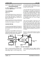
See 

Terminal Housing/Power Cable Reassemb­

ly

 if no further disassembly is required.

Intermediate And Motor Housing Disassembly

(Figure E-1)

See 

PUMP END DISASSEMBLY

, and remove all

pump end and seal components.

With the pump end disassembled and the motor
cavity drained of oil, secure the pump in an in­
verted position. Remove the hardware (46 and 47)
securing the intermediate (50) to the motor hous­
ing (19). 

Do not

 remove the hardware (48 and 49)

around the rotor shaft (39) at this time.

Hook a three‐leg‐sling in the intermediate flange
holes and hoist the intermediate, rotor and shaft
(39), bearing cap (44) and both ball bearings (38
and 43) from the motor housing as an assembly. If
necessary, tap around the parting surfaces with a
soft faced mallet to loosen the seal between the in­
termediate and motor housing. Remove the motor
housing gaskets (16, 17 and 18).

Cover the motor housing with a clean, lint free cloth
to avoid contamination by dirt or other foreign ma­
terial.

Rotor And Bearing Removal

(Figure E-1)

Set the intermediate and rotor assembly on a clean
work area. Leave the lifting slings attached and re­
duce the tension slightly. Remove the hardware
(48 and 49) securing the bearing cap to the inter­
mediate. Steady the rotor and separate the inter­
mediate. If necessary, tap the impeller end of the
rotor shaft with a soft faced mallet to loosen the
seal between the lower ball bearing (43) and the in­
termediate bore.

To prevent damage during removal from
the shaft, it is recommended that bearings
be cleaned and inspected 

in place

. It is

strongly

 recommended that the bearings

be replaced 

any

 time the shaft and rotor

assembly is removed.

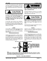
Before removing the bearings from the rotor shaft,
clean and inspect the bearings 

in place

 as follows.

Clean the bearings thoroughly in 

fresh

 cleaning

solvent. Dry the bearings with filtered compressed
air and coat with light oil.

Most cleaning solvents are toxic and
flammable. Use them only in a well ven­
tilated area; free from excessive heat,
sparks, and flame. Read and follow all
precautions printed on solvent contain­
ers.

Rotate the bearings by hand to check for rough­
ness or binding and inspect the bearing balls. If ro­
tation is rough or the bearing balls discolored, re­
place the bearings.

The bearing tolerances provide a tight press fit
onto the shaft and a snug slip fit into the motor
housing and bearing bore. Replace the shaft and
rotor (as an assembly), the motor housing or inter­
mediate if the proper bearing fit is not achieved.

If replacement is required, use a bearing puller to
remove the upper and lower ball bearings from the

Содержание S3C1-E6.2 230/3

Страница 1: ...2008 Rev C March 10 2020 GORMAN RUPP PUMPS www grpumps com 2008 Gorman Rupp Pumps Printed in U S A INSTALLATION OPERATION AND MAINTENANCE MANUAL WITH PARTS LIST SUBMERSIBLE PUMPS MODELS S4B1 E50 460...

Страница 2: ...rial number and e mail address required RECORD YOUR PUMP MODEL AND SERIAL NUMBER Please record your pump model and serial number in the spaces provided below Your Gorman Rupp distributor needs this in...

Страница 3: ...ox Specifications PAGE B 7 Motor Cable Grounding Test PAGE B 7 Control Box Connections PAGE B 7 Liquid Level Devices PAGE B 7 WIRING DIAGRAMS PAGE B 8 OPERATION SECTION C PAGE C 1 GENERAL INFORMATION...

Страница 4: ...d and Strainer Plate Installation PAGE E 12 Strainer Screen and Base Plate Installation PAGE E 12 MOTOR DISASSEMBLY PAGE E 12 Terminal Housing and Power Cable Removal and Disassembly PAGE E 13 Interme...

Страница 5: ...r in other lit erature accompanying the unit please contact your Gorman Rupp distributor or the Gorman Rupp Company The Gorman Rupp Company P O Box 1217 Mansfield Ohio 44901 1217 Phone 419 755 1011 or...

Страница 6: ...result in minor personal injury or product or property damage These instructions de scribe the requirements and the possible damage which could result from failure to follow the procedure NOTE Instru...

Страница 7: ...pump or endan ger personnel as a result of pump fail ure Consult the factory for specific ap plication data Before connecting any cable to the con trol box be sure to ground the control box Refer to...

Страница 8: ...led make certain that the pump and all piping or hose connections are secure before op eration Obtain the services of a qualified elec trician to troubleshoot test and or ser vice the electrical compo...

Страница 9: ...d hertz indicated on the name plate match the ratings on the control box and incoming pow er e Carefully read all tags decals and markings on the pump and perform all duties indicated f Check for oil...

Страница 10: ...oltage Phase 460 3 575 3 S4B Approximate Weight Lbs kg Oil Capacity Ounces Liters Seal Cavity Filling Position H orizontal V ertical Pump 50 Ft Cable Seal Cavity Motor Cavity 741 336 43 20 160 4 7 256...

Страница 11: ...olves a lot of debris protect the pump from excessive wear and clogging by sus pending it in a perforated barrel or culvert pipe If the bottom is heavily sludge covered rest the pump on support blocks...

Страница 12: ...be sub merged Refer to the control box manual for enclo sure dimensions and parts Secure the control vertically on a level surface above flood level The box should be easily acces sible to the operat...

Страница 13: ...on cable clamps and cable Grounding Methods Electrically ground the installation before connect ing the field wiring to the control box Install a grounding terminal to the enclosure and connect it to...

Страница 14: ...position and locked out or that the power supply to the control box has been otherwise cut off and locked out before connecting power or accessory cables The pump is provided with a 50 ft 15 2 m power...

Страница 15: ...tion through an approved control box Ground and wire the control box in accordance with the instructions accompanying it NOTE For reference internal motor wiring connections are shown in Maintenance a...

Страница 16: ...BOX LIQUID LEVEL RANGE OFF DEWATERING ON FILLING DIAPHRAGM TYPE Figure B 4 Liquid Level Devices The internal wiring of the sensing devices are different for filling and dewatering func tions Be sure...

Страница 17: ...automatic liquid level sensing device in which case those circuits are also contained within the control box The pump motor and control box are not designed to be explosion proof Do not operate in an...

Страница 18: ...pump immediately 2 Ventilate the area 3 Allow the pump to completely cool 4 Check the temperature before ser vicing 5 Vent the pump slowly and cau tiously 6 Refer to instructions in this manual befor...

Страница 19: ...the integral thermal over load device will shut off the motor if the temperature rises above design limits When the pump cools and the tempera ture falls below these limits the motor will restart auto...

Страница 20: ...the oil level s as indicated in the following LUBRICATION section COLD WEATHER PRESERVATION Do not attempt to thaw the pump by us ing a torch or other source of flame This could damage gaskets O ring...

Страница 21: ...ding Oil Refer to Table B 2 in INSTALLATION for oil ca pacities and positions for filling the seal cavity in your pump Motor cavities requiring lubrication should always be positioned vertically for f...

Страница 22: ...26 000 volts min Acceptable alternate suppliers Gulf Oil Company Gulf Harmony HVI AW 26 Texas Oil Company Rando HD 32 or HD AZ 32 Sun Oil Company Sunvis 816 or 916 BP Also Boron Energol HLP 32 Shell O...

Страница 23: ...sing device s Float type sensing device s tangled or obstructed Check installation for free movement of float Defective liquid level sensing de vice s or control panel Repair or replace defective unit...

Страница 24: ...or tank Stop pump until liquid level rises Worn impeller vanes excessive im peller clearance Check impeller and clearance see PUMP END REASSEMBLY in Maintenance and Repair Section E Pump running back...

Страница 25: ...under each condition must be the same b If voltage is balanced when the pump is off but is imbalanced when the pump is running thoroughly check the power source all inter connecting cables and the pum...

Страница 26: ...le and motor windings If resistance reads infinity 1 insulation is good If resistance reads between infinity 1 and 1 megohm insulation is acceptable but should be rechecked regularly If resistance rea...

Страница 27: ...ater at sea level with minimum suction lift Since pump installations are seldom identical your performance may be dif ferent due to such factors as viscosity specific gravity elevation temperature and...

Страница 28: ...S SERIES PUMPS OM 06099 MAINTENANCE AND REPAIR PAGE E 2 SECTION DRAWING PARTSPAGE Figure E 1 S4B1 E50 460 3 And S4B1 E50 575 3 Pump Assemblies...

Страница 29: ...RELIEF VALVE 14139 1 33 FILL TUBE ASSY 10040 24040 1 34 HEAVY PIPE NIPPLE THA1612 15079 1 35 STUD C0607 15991 6 36 DEFORM LOCKNUT DD06 15991 6 37 TERM HSG CABLE ASSY 47367 059 1 38 UPPER BALL BEARING...

Страница 30: ...S SERIES PUMPS OM 06099 MAINTENANCE AND REPAIR PAGE E 4 SECTION DRAWING Figure E 2 Terminal Housing And Cable Assembly...

Страница 31: ...ERMINAL HOUSING 11366 13040 1 9 TERMINAL S1949 1 10 HEAT SHRINK TUBE 31413 014 19530 3 11 AL HD SETSCREW GA0501 1 2 14990 3 12 TERMINAL COLLAR 10144 14100 3 13 TERMINAL PLT ASSY 11163 24010 1 14 TERMI...

Страница 32: ...ect a flexible discharge hose before removing the pump If rigid discharge piping is used disconnect the piping before attempting to move the pump Do not attempt to lift the pump by the motor power cab...

Страница 33: ...an any dirt from around the plugs Remove the seal cavity drain plug 12 and install a short 3 8 inch NPT nipple in the hole Tip the pump and drain the seal oil into a clean con tainer Inspect the oil f...

Страница 34: ...bly is required proceed to the appropriate areas in PUMP END REASSEMB LY Upper Seal Removal Figures E 1 and E 3 Unless cracked or otherwise worn it is not neces sary to remove the intermediate 50 for...

Страница 35: ...cks Remove nicks and burrs with a fine file or hand honing stone to restore original contours If the shaft is bent or severely damaged the rotor and shaft must be replaced as an assem bly see MOTOR DI...

Страница 36: ...bent or damaged the complete rotor and shaft must be replaced as an assembly Apply a light coating of oil to the bore of the intermediate Carefully remove the material stuffed into the seat bore or u...

Страница 37: ...eal face to ensure that it is clean and dry If cleaning is necessary use clean tissue to wipe lightly in a cir cular pattern NOTE When pressing seal components onto the rotor shaft use hand pressure o...

Страница 38: ...ired Install the impeller and suction head and recheck impeller clearance NOTE If the intermediate and rotor assembly 50 and 39 were not removed from the motor housing during pump end disassembly allo...

Страница 39: ...motor housing No further disassembly is required to test the stator or power cable To disconnect the power cable 2 remove the nuts 5 securing the terminal gland 1 to the terminal housing 8 Slide the...

Страница 40: ...ing Remove the motor housing gaskets 16 17 and 18 Cover the motor housing with a clean lint free cloth to avoid contamination by dirt or other foreign ma terial Rotor And Bearing Removal Figure E 1 Se...

Страница 41: ...s lay it on its side Do not attempt to rewind the stator Wind ing tolerances and materials are closely controlled by the manufacturer and any deviation can cause damage or operating problems Replace t...

Страница 42: ...of varnish from the ends of the stator before installation to ensure proper stack up height when assembled Position an expandable tool such as a split disc approximately 2 inches 51 mm down inside the...

Страница 43: ...the shaft Use caution when handling hot bear ings to prevent burns If heating the bearing is not practical use a suitably sized sleeve and an arbor or hydraulic press to install the bearing on the sh...

Страница 44: ...n the bearing cap mounting holes Using a three leg sling and lifting eyes in the inter mediate flange holes carefully lower the intermedi ate over the shaft and lower bearing guiding the studs in the...

Страница 45: ...ble potting kit may be used to bond the con nections to the terminal plate If this alternate seal ing method is used refer to the instructions in Seal ing Terminal Plate Connections With Potting Compo...

Страница 46: ...sulting in pump damage and possible serious injury or death to personnel Allow the adhesive to cure for at least one hour be fore securing the terminal housing to the motor housing 2 GREEN TOGETHER IN...

Страница 47: ...collar and lead connections When potting has been completed leave the ter minal plate assembly undisturbed until the potting material has cured Complete curing usually takes about 24 hours Curing time...

Страница 48: ...the cavities If a vacuum pump is not available a compressor venturi system may be used If the compressor venturi cannot draw the higher vacuum level shown in Table E 1 draw the motor cavity vacuum dow...

Страница 49: ...r the color milky or dark refer to Drain ing Oil From Seal Cavity in this section for instruc tions and troubleshooting tips If the oil is clear ap ply Loctite Pipe Sealant With Teflon No 592 or equiv...

Страница 50: ...C 40 to 50 Recommended supplier Gulf Oil Company Gulf Harmony 32 AW ARCO Duro 32 Exxon Also Esso Nuto H 32 Petro Canada Harmony HVI 22 Motor Housing Cavity With the pump in an upright position remove...

Страница 51: ...For Warranty Information Please Visit www grpumps com warranty or call U S 419 755 1280 Canada 519 631 2870 International 1 419 755 1352 GORMAN RUPP PUMPS...

Отзывы: