STEP 5 - TETHER TRACK® INSTALLATION
5.1
Refer to the enclosed General Arrangement Drawing to plan the sequence in which the monorail sections will
be installed. Monorail sections that have splice plate style connections (Z and ZD styles) may need to be
assembled to the mating monorail section prior to lifting and installing on the headers. Do not lift greater than
two assembled (splice plate style connection only) monorail sections at a time. Do not lift assemblies greater
than 54 feet long. Do not allow more than 13 feet of track to extend past the header without support. For
sleeve and truss plate style connections (S, SL, SLX and SLD styles), only lift these sections individually (not
assembled).
Splice Joint Plate Style Connections
5.2
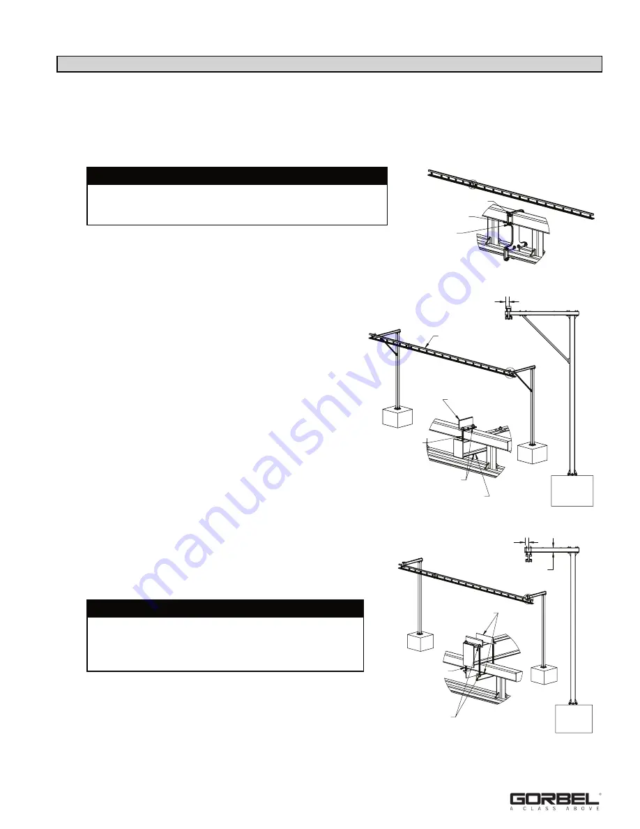
Align mating monorail sections and install hardware (
diagram 5A
).
Verify track flanges (trolley wheel running surfaces) are aligned
before tightening. Run a finger on the inside of the track flange and
use a soft blow mallet to align plates until no lip is
felt. Also check alignment of mating sections for bow
and camber. Steel shims (by others) may be used
between the splice plates to adjust any
misalignment. Tighten hardware to 50 ft.-lbs. of
torque per nut.
Monorail to Header Connections
5.3
The first monorail section(s) to install shall be
connected to two headers. Subsequent sections will
be splice connected to the previously installed
section and a header.
Diagram 5B
shows the top
tube on top of the header.
Diagram 5C
shows the
top tube below the header. Refer to the enclosed
General Arrangement Drawing to determine the
correct orientation. Threading the header through
the monorail truss (
diagram 5B
) is the most
common. When there is at least a 1-1/2” clearance
between the header’s oversized end plate and the
space between the track and top tube on the truss,
the threaded orientation is used. The monorail centerline
should be located from the end of the header as
shown in
diagram 5B
, for threaded mounting or as
shown in
diagram 5C
, for under hung mounting.
5.4
Using proper rigging practices (by others) lift the monorail
section(s) into place and secure to the header using spine
clamp angles, clamp plates, and hardware provided
(
diagrams 5B
and
5C
).
Note:
For outdoor systems, all hardware may not be
galvanized. You will need to use cold galvanizing spray
provided on any unplated/galvanized hardware (refer to
steps 1.5
and
1.6
, page 4).
TOP TUBE
4 1/2" FOR TOP TUBE WIDTH <= 3"
5 1/2" FOR TOP TUBE WIDTH <= 5"
6 3/4" FOR TOP TUBE WIDTH > 5"
SPINE CLAMP ANGLE
SQUARE CLAMP PLATE
5/8"-11 THREADED ROD
FLAT WASHER & LOCK NUT (OUTDOOR)
LOCK WASHER & HEX NUT (INDOOR)
Diagram 5B.
Installing threaded monorail.
9
9/18 Rev B
6 3/4" FOR 8" HEADER DEPTH
5 1/2" FOR SMALLER HEADERS
HEADER DEPTH
SPINE CLAMP ANGLES
FLAT WASHER &
LOCK NUT (OUTDOOR)
LOCK WASHER &
HEX NUT (INDOOR)
5/8"-11 THREADED ROD
Diagram 5C.
Installing under hung monorail.
1/2"-13 X 1-1/2" HHCS
FLAT WASHER
LOCK NUT
Diagram 5A.
Plate style splice joint detail.
WARNING
The locations of the runways cannot deviate from the locations
shown on the drawing. Changing the locations will void the
design and the warranty.
WARNING
The largest monorail assembly required to install may be
54 feet long and weigh 1300 lbs. Do not perform
installations under adverse weather conditions or without
the proper lifting equipment.


