


6
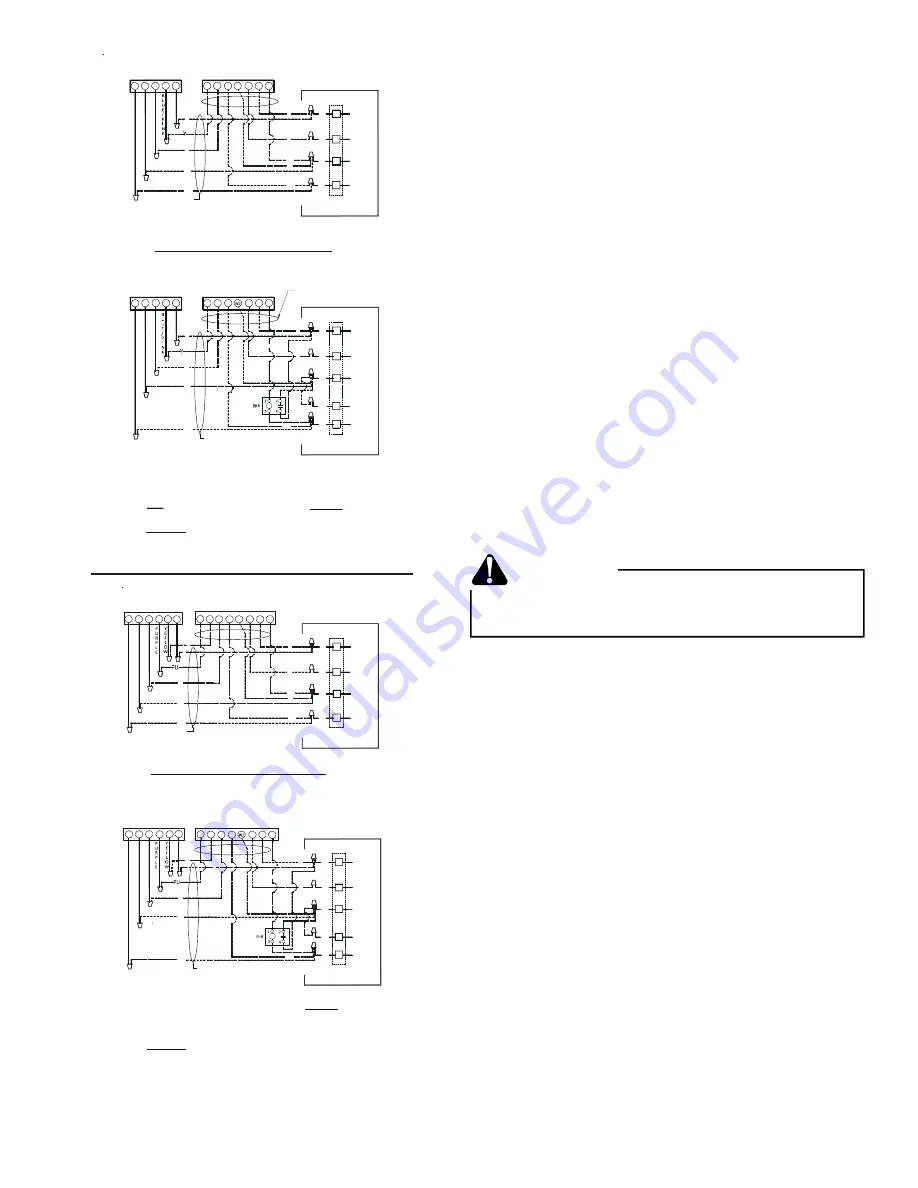
NOTES:
1) TERMINAL BLOCK MARKINGS ARE FOR GOODMAN/AMANA
AIR HANDLERS.
NOMENCLATURE
EHR -EMERGENCY HEAT RELAY (OPTIONAL)
COLOR CODES
BL-- BLUE
BR--BROWN
GR--GREEN
OR--ORANGE
RD--RED
WH-WHITE
Y--YELLOW
BL/PK--BLUE/PINK STRIPE
O
R
A
N
G
E
#18 GA. 5 WIRE
BL
O
W
BL
W
G
C
BLUE
W2
G
WHITE
GREEN
ROOM THERMOSTAT
HEAT PUMP
B
L
U
E
W
H
I
T
E
R
E
D
R
#18 GA. 7 WIRE
R
INDOOR UNIT
R
RED
W3
BROWN
BR
R
G
BR
BL
W2
C
O
Y
R
Y
O
C
G
R
E
SYSTEM COMPOSITE DIAGRAM - ALL SIZES (EXCEPT 5T 16 SEER) HEAT PUMPS - ABOVE 10 KW
W2
TYPICAL H/P
ROOM THERMOSTAT
HEAT PUMP
R
G
C
W2
RED
GREEN
WHITE
BLUE
INDOOR UNIT
R
O
W
BL
#18 GA. 5 WIRE
R
G
BR
W
BL
R
E
D
O
R
A
N
G
E
W
H
I
T
E
B
L
U
E
BL
W
G
R
C
O
Y
R
Y
O
C
W2
G
R
E
SYSTEM COMPOSITE DIAGRAM - ALL SIZES (EXCEPT 5T 16 SEER) HEAT PUMPS - 10 KW & BELOW
NOTES:
1) TERMINAL BLOCK MARKINGS ARE FOR GOODMAN/AMANA
AIR HANDLERS.
NOMENCLATURE
EHR -EMERGENCY HEAT RELAY (OPTIONAL)
COLOR CODES
BL-- BLUE
BR--BROWN
GR--GREEN
OR--ORANGE
PU--PURPLE
RD--RED
WH-WHITE
Y--YELLOW
BL/PK--BLUE/PINK STRIPE
O
R
A
N
G
E
#18 GA. 5 WIRE
BL
O
W
ROOM THERMOSTAT
HEAT PUMP
B
L
U
E
W
H
I
T
E
W2
C
O
Y
Y
Y2
Y
BL
W
G
C
BLUE
W2
G
WHITE
GREEN
R
INDOOR UNIT
R
RED
W3
BROWN
BR
R
G
BR
BL
O
C
G
R
E
SYSTEM COMPOSITE DIAGRAM - 5T 16 SEER ONLY HEAT PUMPS - ABOVE 10 KW
W2
ROOM THERMOSTAT
HEAT PUMP
R
O
W
BL
#18 GA. 5 WIRE
O
R
A
N
G
E
W
H
I
T
E
B
L
U
E
C
O
Y
R
E
D
R
Y
R
G
C
W2
RED
GREEN
WHITE
BLUE
INDOOR UNIT
R
G
BR
W
BL
BL
W
G
R
O
C
W
G
R
E
SYSTEM COMPOSITE DIAGRAM - 5T 16 SEER ONLY HEAT PUMPS - 10 KW & BELOW
Y2
Y2
Y
R
E
D
R
R
Y2
Thermostat
with Low Voltage Wires to Heat Pump Unit
System Start Up
NOTE:
Units with crankcase heaters should have high
voltage power energized for 24 hours prior to start up.
Heat pumps are equipped with a time/temperature defrost
control with field selectable defrost intervals of 30, 60, or
90 minutes. This setting should be adjusted at this time if
needed. The defrost control also has SmartShift
™
technology, which delays compressor operation at defrost
initiation and termination. If disabling this function is
desired, move the jumper from
“
DLY
”
to
“
NORM
”
on the
defrost control
Adequate refrigerant charge for the matching HSVTC evapora-
tor coil and 15 feet of lineset is supplied with the condensing
unit. If using evaporator coils other than HSVTC coil, it may be
necessary to add or remove refrigerant to attain proper charge.
If line set exceeds 15 feet in length, refrigerant should be added
at .6 ounces per foot of liquid line.
NOTE:
Charge should always be checked using superheat when
using a piston and subcooling when using TXV equipped in-
door coil to verify proper charge.
Open the suction service valve first! If the liquid service valve is
opened first, oil from the compressor may be drawn into the
indoor coil TXV, restricting refrigerant flow and affecting opera-
tion of the system.
POSSIBLE REFRIGERANT LEAK
To avoid a possible refrigerant leak, open the service
valves until the top of the stem is 1/8
”
from the retainer.
CAUTION
When opening valves with retainers, open each valve only until
the top of the stem is 1/8
”
from the retainer. To avoid loss of
refrigerant, DO NOT apply pressure to the retainer. When open-
ing valves without a retainer remove service valve cap and in-
sert a hex wrench into the valve stem and back out the stem
by turning the hex wrench counterclockwise. Open the valve
until it contacts the rolled lip of the valve body.
NOTE:
These are not back-seating valves. It is not necessary
to force the stem tightly against the rolled lip.
After the refrigerant charge has bled into the system, open the
liquid service valve. The service valve cap is the secondary seal
for the valve and must be properly tightened to prevent leaks.
Make sure cap is clean and apply refrigerant oil to threads and
sealing surface on inside of cap. Tighten cap finger-tight and
then tighten additional 1/6 of a turn (1 wrench flat), or to the
following specification, to properly seat the sealing surfaces.
1. 3/8
”
valve to 5 - 10 in-lbs
2. 5/8
”
valve to 5 - 20 in-lbs
3. 3/4
”
valve to 5 - 20 in-lbs
4. 7/8
”
valve to 5 - 20 in-lbs
Do not introduce liquid refrigerant from the cylinder into the
crankcase of the compressor as this may damage the
compressor.