


10
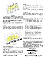
Fu rnace
Water
Heater
Outlet Air
Chimney o r Gas Vent
NOTE: The inlet and outlet air
openings must each have a free
area of not less than one square
inch per 4000 BTU of the
total input rating of all equipment
in the enclosure.
Inlet air duct
[ends 1 ft (3 00 mm)
above floor]
Ventilation louvers
(each end of attic)
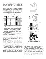
Equipment Located in Confined Spaces; All Air from Outdoors
Through Ventilated Attic. See 5.3.3-b.
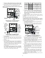
3. When communicating with the outdoors through horizontal ducts,
each opening shall have a minimum free area of 1 square inch per
2,000 BTU per hour of total input rating of all equipment in the
enclosure.
Furnace
Water
Heater
Chimney or Gas Vent
NOTE: The air duct openings
must have a free area of not
less than one square inch per
2000 BTU of the total input
rating of all equipment in the
enclosure*.
Outlet air duct
Inlet air duct
*If the appliance room is located against an outside wall and the air openings communicate directly with the
outdoors, each opening shall have a free area of not less than one square inch per 4,000 BTU per hour of
the total input rating of all appliances in the enclosure.
Equipment Located in Confined Spaces; All Air from Outdoors.
See 5.3.3-b.
4. When ducts are used, they shall be of the same cross-sectional
area as the free area of the openings to which they connect. The
minimum dimension of rectangular air ducts shall not be less
than 3 inches.
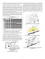
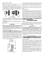
Furnace
Water
Heater
Opening
Chimney or Gas Vent
NOTE: The single opening must have
a free area of not less than one
square inch per 3000 BTU of
the total input rating of all equip-
ment in the enclosure, but not less than
the sum of the areas of all vent
connectors in the confined space.
Alternate
Opening
Location
Equipment Located in Confined Spaces; All Air from Outdoors -
Single Air Opening. See 5.3.3-b.
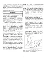
5.3.3 Equipment Located in Confined Spaces:
(a)
All Air from Inside the Building:
The confined space shall be pro-
vided with two permanent openings communicating directly with
an additional room(s) of sufficient volume so that the combined
volume of all spaces meets the criteria for an unconfined space. The
total input of all gas utilization equipment installed in the combined
space shall be considered in making this determination. Each open-
ing shall have a minimum free area of 1 square inch per 1,000 BTU
per hour of the total input rating of all gas utilization equipment in
the confined space, but not less than 100 square inches. One open-
ing shall be within 12 inches of the top and one within 12 inches of
the bottom of the enclosure.
Furnace
Water
Heater
Opening
Chimney or Gas Vent
Opening
NOTE: Each opening must have
a free area of not less than one
square inch per 1000 BTU of
the total input rating of all equip-
ment in the enclosure, but not
less than 100 square inches.
Equipment Located in Confined Spaces; All Air from Inside
Building. See 5.3.3-a.
(b)
All Air from Outdoors:
The confined space shall be provided with
two permanent openings, one commencing within 12 inches of the
top and one commencing within 12 inches of the bottom of the
enclosure. The openings shall communicate directly, or by ducts,
with the outdoors or spaces (crawl or attic) that freely communicate
with the outdoors.
1. When directly communicating with the outdoors, each opening
shall have a minimum free area of 1 square inch per 4,000 BTU
per hour of total input rating of all equipment in the enclosure.
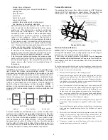
Furnace
Water
Heater
Outlet Air
Chimney or Gas Vent
NOTE: The inlet and outlet air
openings must each have a free
area of not less than one square
inch per 4000 BTU of the
total input rating of all equipment
in the enclosure.
Inlet Air
Ventilation louvers for
unheated crawl space
Alternate
air inlet
Ventilation louvers
(each end of attic)
Equipment Located in Confined Spaces; All Air from Outdoors—
Inlet Air from Ventilated Crawl Space and Outlet Air to Ventilated
Attic. See 5.3.3-b
2. When communicating with the outdoors through vertical ducts,
each opening shall have a minimum free area of 1 square inch per
4,000 BTU per hour of total input rating of all equipment in the
enclosure.