61
•
The circulator if already running remains energized at
the current CFM for the circulator fan off delay period.
•
When the Inter-purge Period expires, the control pro-
ceeds to the HSI Warm-up and then a new Trial for
Ignition is started.
•
A maximum of two recycles (3 flame losses) are al-
lowed on a single call for heat before the control pro-
ceeds to Soft Lockout through the Post-purge where
the inducer remains energized at the current speed.
Error code “E0” is flashed during the Soft Lockout pe-
riod.
•
The recycle count is not cleared until the current de-
mand for heat is satisfied or upon exit of Soft Lockout.
Rollout Circuit Operation
If the manual reset rollout switch circuit opens during a heat-
ing cycle:
•
The valve is immediately de-energized.
•
The inducer will run for the Post-purge period at its
current speed
•
If the circulator fan is on it will run for the normal fan off
delay at the current heat speed.
•
An error code is logged and displayed indicating the
rollout switch circuit has opened.
•
All future thermostat heat requests are ignored..
The IFC will remain in this state until the rollout switch
closes. Once the manual rollout switch has been re-
set the IFC will clear the error code and return to nor-
mal operation.
If the rollout switch circuit opens in any mode, other than
Heat, it will be ignored.
Limit Switch Operation
If the limit switch circuit is open during a heating cycle:
•
The valve is immediately de-energized.
•
The inducer will run for the Post-purge period at its
current speed.
•
The circulator is immediately energized at high heat
speed. The IFC will remain in this state until the limit
switch circuit closes.
•
The IFC logs and displays an error code indicating the
limit circuit is open.
•
Once the limit switch circuit closes and a call for heat
is present, a new ignition sequence is started and the
circulator will remain energized for the selected fan off
delay. If the burner is lit before expiration of the se-
lected fan off delay, the fan off timing is stopped and
the circulator will adjust to the speed requested by the
heating sequence.
If the limit switch circuit opens in any mode, other than Heat,
it will be ignored.
Pressure Switch Configuration
•
The IFC monitors the contacts of a SPST (single pole
single throw) low pressure switch with a set point that
ensures the switch will be closed at approximately 35%
of the firing rate of the furnace.
•
The IFC monitors the contacts of a SPST high pres-
sure switch with a set point that ensures the switch
will be closed at approximately 100% of the firing rate
of the furnace.
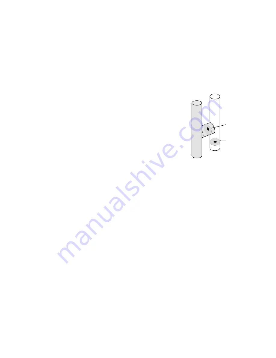
H Fitting
Restricting Orifice
Restricting Orifice
The H-fitting
“conditions”
the negative
pressure
signal which
is applied to
the gas valve
"H" Fitting
The low pressure switch assembly includes an H fitting as-
sembly and tubing that provides pressure signals to the
Honeywell amplified gas/air gas valve. The H fitting contains
an orifice which conditions the negative air pressure control-
ling the gas valve. This has the effect of allowing only smooth
changes in air pressure to reach the gas valve.
Low Pressure Switch Operation
•
If a call for heat exists and the low pressure switch is
closed already (before the ignition sequence has be-
gun), the IFC will wait 5 minutes. After the 5 minute
delay, and if the LPS is still closed, the IFC will log
and display an error code indicating the low pressure
switch is stuck closed. When the LPS is sensed open,
the IFC clears the error code and resumes normal op-
eration.
If the ignition sequence has begun and the low pressure switch
fails to close within 30 seconds, the IFC logs and displays
an error code indicating the low pressure switch is stuck
open. The inducer continues to run for a total of 5 minutes,
at which time the IFC de-energizes the inducer and then at-
tempts the Calibration routine immediately. If during the 5
minute interval LPS is sensed closed or call for heat is re-
moved, the IFC clears the error code and resumes normal
operation.
SERVICE & OPERATION


