SERVICING
42
If either winding does not test continuous, replace the
compressor.
NOTE:
If an open compressor is indicated, allow ample
time for the internal overload to reset before replacing
compressor.
S-17B GROUND TEST
If fuse, circuit breaker, ground fault protective device,
etc., has tripped, this is a strong indication that an
electrical problem exists and must be found and cor-
rected. The circuit protective device rating must be
checked, and its maximum rating should coincide with
that marked on the equipment nameplate.
With the terminal protective cover in place, it is accept-
able to replace the fuse or reset the circuit breaker ONE
TIME ONLY to see if it was just a nuisance opening. If
it opens again, DO NOT continue to reset.
WARNING
Disconnect ALL power before servicing.
Disconnect all power to unit
, making sure that
all
power legs are open.
1. DO NOT remove protective terminal cover. Discon-
nect the three leads going to the compressor termi-
nals at the nearest point to the compressor.
2. Identify the leads and using a Megger, Hi-Potential
Ground Tester, or other suitable instrument which
puts out a voltage between 300 and 1500 volts, check
for a ground separately between each of the three
leads and ground (such as an unpainted tube on the
compressor). Do not use a low voltage output
instrument such as a volt-ohmmeter.
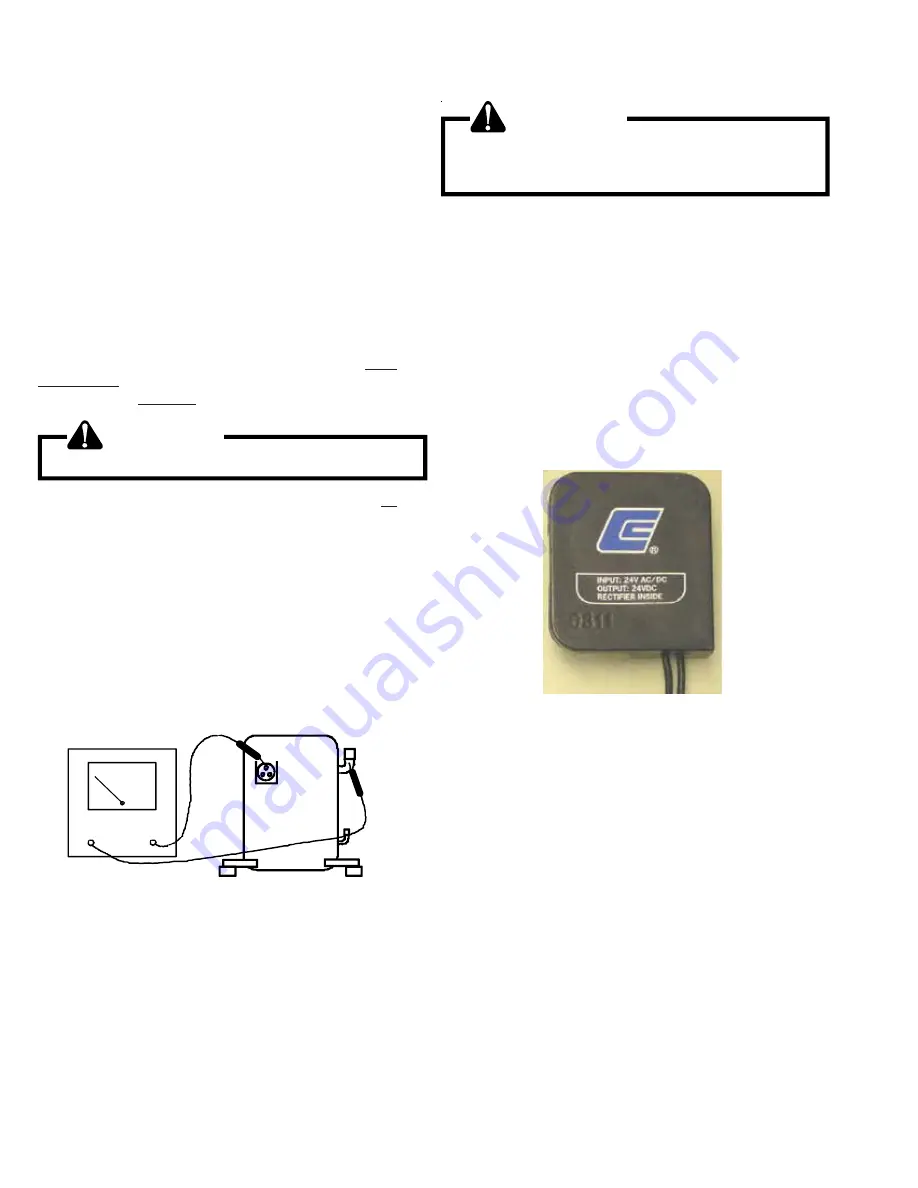
HI-POT
COMPRESSOR GROUND TEST
3. If a ground is indicated, then carefully remove the
compressor terminal protective cover and inspect for
loose leads or insulation breaks in the lead wires.
4. If no visual problems indicated, carefully remove the
leads at the compressor terminals.
WARNING
Damage can occur to the glass embedded terminals if
the leads are not properly removed. This can result in
terminal and hot oil discharging.
Carefully retest for ground, directly between compressor
terminals and ground.
5. If ground is indicated, replace the compressor.
S-17C UNLOADER TEST PROCEDURE
(2 STAGE COMPRESSORS ONLY)
A nominal 24-volt direct current coil activates the internal
unloader solenoid. The input control circuit voltage must be
18 to 28 volt ac. The coil power requirement is 20 VA. The
external electrical connection is made with a molded plug
assembly. This plug contains a full wave rectifier to supply
direct current to the unloader coil.
U NL OADER SO LEN OID
(M olded Plug)
Unloader Test Procedure
If it is suspected that the unloader is not working, the following
methods may be used to verify operation.
1. Operate the system and measure compressor current.
Cycle the unloader ON and OFF at 10 second intervals.
The compressor amperage should go up or down at least
25 percent.
2. If step one does not give the expected results, shut unit
off. Apply 18 to 28 volt ac to the unloader molded plug
leads and listen for a click as the solenoid pulls in.
Remove power and listen for another click as the unloader
returns to its original position.
3. If clicks can’t be heard, shut off power and remove the
control circuit molded plug from the compressor and
measure the unloader coil resistance. The resistance
should be 32 to 60 ohms, depending on compressor
temperature.


