3
HARDWARE INSTALLATION
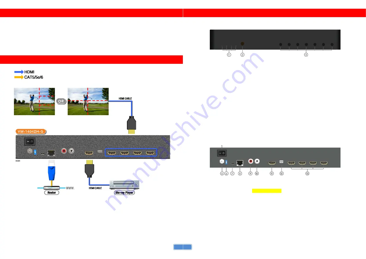
VW-1404ZH-G as master
1. Connect the sources to HDMI / DisplayPort Input of the VW-1404ZH-G.
2. Connect all displays to HDMI Outputs of the VW-1404ZH-G.
3. Connect the +12V DC power supply to the VW-1404ZH-G.
CONNECTION DIAGRAM
4
PANEL DESCRIPTIONS
Front Panel
1.
LED indicator:
PWR – Power indicator LED
LOCK – When device status is locked, it will shine
4K – If source resolution is 4K, the LED indicator will shine
Source – When source from HDMI, the LED indicator will shine
Source from DisplayPort, the LED indicator will blink
2.
IR SENSOR:
IR sensor for receiving the IR commands from IR remote
3.
Control buttons:
Button 1 (Source) –
Source setting (HDMI or DisplayPort)
Button 2 (LOCK) –
Press button for 3 seconds will enable/disable device locked
Button 3 (2x2) – Fast switch to 1x1 and 2x2
Button 4 (+90°) – Fast switch to 3x1 90° and 4x1 90°
Button 5 (-90°) – Fast switch to 3x1 -90° and 4x1 -90°
Button 6 (Preset 1)
Button 7 (Preset 2)
Rear Panel
4.
Power Switch:
Power ON/OFF switch
5.
+12V DC:
12V DC power jack
6.
Dip Switch:
For firmware update (Default mode: ON)
7.
USB virtual COM
8.
Ethernet:
Ethernet control port
9.
Stereo audio output – L
10.
Stereo audio output – R
11.
HDMI INPUT
12.
DisplayPort INPUT
13.
Output 1-4:
HDMI outputs


