


- 27 -
- 28 -
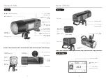
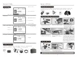
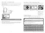
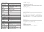
Name of Parts
Name of Parts
Body:
Body:
Fan Inlet
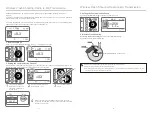
(1) TTL Autoflash
TTL
:
TTL
Autoflash
Body:
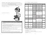
LCD Panel:
Flash
exposure
compensation
amount
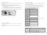
Direction
Adjusting Handle
High Speed Sync
Umbrella
Mounting Hole
<
MODE
> Mode Selection Button
< >
Modeling Lamp Button
<
>Power Switch
<
MENU
> Menu Button
<
GR/CH
>
Group/Channel
Button
Select Dial
<
SET
>Set Button
< >
Test Button /
Flash Ready Indicator
< >
Wireless
Selection Button
Accessory
Mount
Tube Socket
Modeling
Lamp (LED)
Light Sensor
CH
1
TTL
A
+0.3
10
%
<
H
>
High Speed
Sync Button
Bracket Locking Ring
Socket for
Portable Flash Head
Battery
Indicator
Button
Accessory
Locking Ring
Type-C USB Port
3.5mm Sync Cord Jack
Mounting Bracket
Lithium Battery
Battery Locking
Ring
Handle Fixed Part
Handle Fixing
Screw
Bracket Fixing
Screw
Mount Fixing Screw
Battery Power
Jack
Fan Outlet
Power Outlet
Power Inlet


